I finished up the first section of wiring assembly - the power supply.
I inserted the 5U4G tube, temporarily hooked it up to power, and slowly turned the voltage up using a Variac. I confirmed getting over 350 VDC from the power supply output, so the power supply is working,
Saturday, April 7, 2018
Thursday, April 5, 2018
Rebuilding The Heathit AT-1 Transmitter - FT-243 Crystal Adaptor
While I was waiting for the tube sockets to arrive so I could get started with assembly, I took a little diversion.
The AT-1 has a socket to accept a crystal in the FT-243 form factor, which was popular at the time it was sold. Since then crystals have generally become smaller, and FT-243 crystals are no longer available. In fact, the demand for radio crystals has gone down significantly in recent years. One of the most well known crystal manufactuers for radio use, International Crystals, founded in 1951, shut down in 2017.
Some FT-243 type crystals are shown here, along with a more modern type meant to be soldered directly into a PCB.
As a little 3D printing project, I spent an evening using openSCAD to design a plastic case that allows a small crystal to be mounted inside, and using a couple of pins from an old octal vacuum tube for ins, turns it into the FT-243 form factor. Here is an example of my prototype.
I put the 3D printer model files here and made them freely available in case anyone else wants to use them.
The AT-1 has a socket to accept a crystal in the FT-243 form factor, which was popular at the time it was sold. Since then crystals have generally become smaller, and FT-243 crystals are no longer available. In fact, the demand for radio crystals has gone down significantly in recent years. One of the most well known crystal manufactuers for radio use, International Crystals, founded in 1951, shut down in 2017.
Some FT-243 type crystals are shown here, along with a more modern type meant to be soldered directly into a PCB.
As a little 3D printing project, I spent an evening using openSCAD to design a plastic case that allows a small crystal to be mounted inside, and using a couple of pins from an old octal vacuum tube for ins, turns it into the FT-243 form factor. Here is an example of my prototype.
I put the 3D printer model files here and made them freely available in case anyone else wants to use them.
Rebuilding The Heathit AT-1 Transmitter - Starting Assembly
Finally the tube sockets arrived, so I could get started with the actual assembly.
The new sockets were a little smaller than the originals and the mounting holes did not quite line up with the existing holes in the chassis. I cut the holes in the sockets into slots using a Dremel tool and cutoff wheel. That made it fit well enough.
As well as the tube sockets and terminal strips, I remounted the transformer and choke, front panel controls and panel.
I'm now ready to start wiring and installing the components.
As well as the tube sockets and terminal strips, I remounted the transformer and choke, front panel controls and panel.
I'm now ready to start wiring and installing the components.
Labels:
amateur radio,
AT-1,
Electronic Kit,
ham radio,
Heathkit,
Transmitter,
vacuum tube
Wednesday, April 4, 2018
Rebuilding The Heathit AT-1 Transmitter - Winding Inductors
As mentioned earlier, I will reuse the original band switch and oscillator coils, power transformer and filter choke. I decided to wind new RF chokes using toroidal cores.
It calls for two 1.1 mH chokes and one 90 uH. I used a little toroid design application I wrote myself and came up with these designs:
1.1 mH: FT-82-43 core, 44 turns, #28 wire.
90 uH: FT-50-43 core, 13 turns, #28 wire.
I wound them and measured the values using my AADE L/C meter. They read a little low so I added a few turns.
One other part I didn't mention earlier - I will replace the line cord with a new one using a brown two-wire extension cord that is similar to the original.
It calls for two 1.1 mH chokes and one 90 uH. I used a little toroid design application I wrote myself and came up with these designs:
1.1 mH: FT-82-43 core, 44 turns, #28 wire.
90 uH: FT-50-43 core, 13 turns, #28 wire.
I wound them and measured the values using my AADE L/C meter. They read a little low so I added a few turns.
One other part I didn't mention earlier - I will replace the line cord with a new one using a brown two-wire extension cord that is similar to the original.
Tuesday, April 3, 2018
Rebuilding The Heathit AT-1 Transmitter - Painting the Chassis
The chassis was very corroded. It is steel plated with copper, and because the corrosion has come through the plating, sanding it will not restore it to as new because the copper is gone in some areas.
It could be replated with copper, but that is quite an effort to go to or an expense to have done commercially by a plating shop.
My solution was just to paint it. After some seartching I was able to find metallic (shiny) copper spray paint at a Michael's craft store. A lot of small coats were applied to the
top, bottom, and sides, until the finish was acceptable.
I also straightened it as it was a little bent (using a hammer protected by a towel).
The paint is not conductive, so I need to scrape it off wherever the tube sockets, terminal strips, and connectors connect to the chassis so that they make a good connection to ground. You can do this with a large drill bit turned by hand, and with a small file for the larger holes like those for the tube sockets.
Monday, April 2, 2018
Rebuilding The Heathit AT-1 Transmitter - Sources for New Parts
I researched and ordered the new parts I would need.
First was a new manual, as there were no complete manuals available on the Internet. I ordered a manual from The Manualman, a source I've used before and which offers very high quality spiral bound reproduction manuals. It arrived within a few days and was very clean and complete with foldout schematic and illustrations.
While I had a few of the necessary capacitors in hand, I ordered the rest from Just Radios. They stocked everything I needed, including the silver mica caps. The order also arrived in a couple of days.
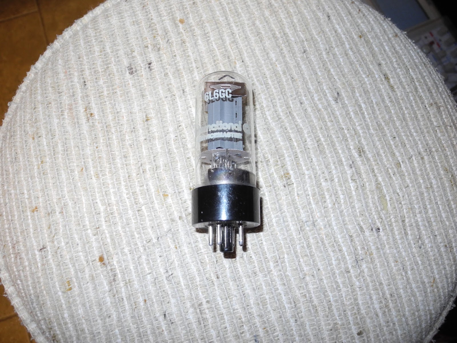
One item that took some research was the 6L6 tube. It is available, but can be expensive because it is also popular with tube-based electric guitar amplifier and hi-fi/stereo enthusiasts. The original metal 6L6 is harder to find than the glass 6L6GC. There seems to be no reason I can't use the 6L6GC and in fact it has better specs, so I opted to go with that. Being in Canada, shipping was quite high from some of the larger tube vendors. I ended up finding a NOS 6L6GC tube on eBay (from a seller in Germany). I have now received it.
Some more searching on eBay found sources for the octal tube sockets and plugs that I needed. These have been ordered but have not yet been received yet (they are coming from China).
I had all the needed resistors on hand.
I will use the original band coils and oscillator coils as they are unique to the AT-1, as well as the variable caps. It appeared that some of the RF chokes in my unit had been replaced with different values (and there were four rather than three -- one appeared to be added as a key click filter). I decided to wind replacements for these myself using toroidal core, which should perform well but not appear original.
I will also keep the power transformer and filter choke.
The terminal strips, jacks, switches, and other assorted hardware will be replaced or the existing ones used depending on condition of the original parts and what I have on hand.
First was a new manual, as there were no complete manuals available on the Internet. I ordered a manual from The Manualman, a source I've used before and which offers very high quality spiral bound reproduction manuals. It arrived within a few days and was very clean and complete with foldout schematic and illustrations.
While I had a few of the necessary capacitors in hand, I ordered the rest from Just Radios. They stocked everything I needed, including the silver mica caps. The order also arrived in a couple of days.
One item that took some research was the 6L6 tube. It is available, but can be expensive because it is also popular with tube-based electric guitar amplifier and hi-fi/stereo enthusiasts. The original metal 6L6 is harder to find than the glass 6L6GC. There seems to be no reason I can't use the 6L6GC and in fact it has better specs, so I opted to go with that. Being in Canada, shipping was quite high from some of the larger tube vendors. I ended up finding a NOS 6L6GC tube on eBay (from a seller in Germany). I have now received it.
Some more searching on eBay found sources for the octal tube sockets and plugs that I needed. These have been ordered but have not yet been received yet (they are coming from China).
I had all the needed resistors on hand.
I will use the original band coils and oscillator coils as they are unique to the AT-1, as well as the variable caps. It appeared that some of the RF chokes in my unit had been replaced with different values (and there were four rather than three -- one appeared to be added as a key click filter). I decided to wind replacements for these myself using toroidal core, which should perform well but not appear original.
I will also keep the power transformer and filter choke.
The terminal strips, jacks, switches, and other assorted hardware will be replaced or the existing ones used depending on condition of the original parts and what I have on hand.
Sunday, April 1, 2018
Rebuilding The Heathit AT-1 Transmitter - Teardown
I took a deep breath and totally tore the unit down to the bare metal chassis.
I removed all wires and components from the terminal strips, switches, tube sockets as I will have to reuse some of them. The component leads were straightened and they were all set aside.
I kept all parts, although I'm not planning to reuse any of the fixed caps or resistors.
While doing so, I noticed a couple of capacitors with open leads - one power supply filter cap and one (large red) mica cap. I'm not sure if these were in this condition before I started the teardown.
I removed all wires and components from the terminal strips, switches, tube sockets as I will have to reuse some of them. The component leads were straightened and they were all set aside.
I kept all parts, although I'm not planning to reuse any of the fixed caps or resistors.
Subscribe to:
Posts (Atom)