Showing posts with label kit. Show all posts

Saturday, April 7, 2018

Rebuilding The Heathit AT-1 Transmitter - Power Supply Wiring

I finished up the first section of wiring assembly - the power supply.


I inserted the 5U4G tube, temporarily hooked it up to power, and slowly turned the voltage up using a Variac. I confirmed getting over 350 VDC from the power supply output, so the power supply is working,

Saturday, April 22, 2017

Commercially Available Enigma Machine Kits

I did some research on Enigma kita on the market. Not counting simulators and mechanical replicas, I found three curently available electronic replica kits. The information below summarizes the different units.


Name: MeinEnigma
Website: http://www.meinenigma.com
Price: TBD
Accessories: TBD
Notable Features:

Arduino-based, 4 alphanumeric LEDs, keyboard, lamps, plugboard, sound, turnable rotors, real-time clock.


Name: Enigma-E
Website: http://www.cryptomuseum.com/kits/index.htm
Price: 150 Euro
Accessories: Case, UhrBox
Notable Features:

Microprocessor (PIC)-based, 4 digit alphanumeric display, 26 keys, LEDs, plugboard.


Name: S&T GeoTronics Enigma Mark 4 (also called OpenEnigma)
Website: http://www.stgeotronics.com/Kits_c8.htm
Price: US$300
Accessories: Plugboard, cables, case, bare PCB
Notable Features:

Arduino-based, 4 alphanumeric LEDs, keyboard, LEDs, cover plate.


Tuesday, April 4, 2017

The MeinEnigma Enigma Machine Kit - Assembly


In this post I'll continue the discussion of the MeinEnigma kit, this time describing my experience in building the kit.

It should be noted that this was for a beta version of the kit. Some changes to the construction method, assembly procedure, and physical parts are planned to be made before the kit goes into general release.

I was the first customer for a beta release of the kit; my unit was serial number 16. As I have a lot of experience building kits and live in the same city (Ottawa, Canada) as the developer, I was a good candidate to try out an early kit and give feedback on it.

This was the hybrid version of the kit, with all through-hole components with the exception of three SMT ICs that need to be soldered.


The kit came in a box with a nice printed label. All parts were included with the exception of batteries.

The PCBs are double-sided with plated-through holes, soldermask, and silkscreen on both sides. The design is somewhat unique in that there are pads for both SMT and through-hole parts.


All the parts come organized in small bags with identifiers on them that match the instructions in the assembly manual. This goes a long way in minimizing any errors in components or needing to identify them.

I made an inventory against the provided parts list and confirmed that all parts were there. The parts are grouped into five sub-assemblies that are built separately (corresponding in most cases to different circuit boards). I separated the parts for each assembly.


One of the reasons this was still considered a beta kit was that the assembly manual was not yet complete. It was in pretty good shape though, with detailed instructions and pictures for all the steps of the construction.

Lamp and Key Board


Construction started with the lamp and key board, the largest PCB but one without too many parts - mostly the 26 keyboard keys and 26 LEDs.

The first step was to install the HT16K33 IC, a 28-pin SMT device. I was a little anxious about this as I have only limited experience with soldering SMT devices by hand. Before installing it I refreshed my memory of SMT soldering techniques by watching some YouTube videos and doing some practice with some SMT parts on a piece of bare copper PCB.

As well as using a temperature controlled soldering iron and small diameter solder, I used some flux paste, applying it to the pads on the board. The initial alignment of the IC is critical. You solder one corner pin, get the chip correctly aligned, then solder the opposite corner. It is important not to proceed with soldering the remaining pins until it is correctly aligned. Soldering the remaining pins should then be quite easy. In the past I have done SMT soldering without paste; I believe the solder paste really helped the solder flow and avoid solder bridges between pins.


I used a digital multimeter in continuity test mode to verify that all the IC pins were making contact with the board and that there were no shorts between pins.

The assembly continued with two diodes and 13 resistors. These were through-hole parts. The SMT version should also be straightforward to solder. Often the biggest challenge with SMT is being able to identify the parts and avoid dropping and losing them.


Next there are 26 keyboard switches and 26 LEDs to install, and then some connectors. The last step is to install the four standoff feet and then assembly of this board is complete.

Encoder Boards


The four wheels, known as rotors, use rotary encoders. Each encoder is installed on a small custom PCB which is later connected to the main board using a four pin connector and a plastic bracket. Each board needs to have the encoder and connector soldered in. They are then set aside until final assembly. This step went smoothly.

Main Board


The main board has the most components. It starts with some through-hole components including fuses, a diode, and resistors. Two DIP ICs are installed using sockets. There are a number of connectors to install, and then an Arduino Nano (or equivalent clone) which is mounted on headers so it can be removed if needed. A sound board is installed, then the DC-DC boost convertor which is on a small PCB.


Other parts installed are a large filter capacitor, four keyswitches, a small speaker and piezo buzzer, the "big red switch", rotary function switch, and the four alphanumeric LED displays.

Construction wraps up with the battery holder and real-time clock module.


You can now complete the mechanical assembly of the main board by installing the standoff feet and assemble the rotors by inserting the wooden disks on the encoders, and then installing each of the four rotors to the main board using a plastic bracket.


Incidently, the four rotors are made from wood and laser cut. This is one of the features that makes the kit a more realistic replica of the original Enigma than some designs that just use buttons.

At this point the two PCBS can be connected using a ribbon cable and the system can be tested. Before doing so, I carefully inspected everything for opens, shorts, and incorrect components or orientation.

Plugboard and Cables


There is still one PCB to be assembled, the plugboard.

It has two more SMT ICs to solder. I wasn't entirely pleased with the job I did on the first IC on the lamp/key board, but I must have improved with practice because these ICs were better aligned. I did have to reflow the solder on some of the pins on the SMT ICs to ensure all were making good connections.

This board also has 26 suppressor diodes, a connector, and 26 banana jacks to install (the latter do not need to be soldered).


The plugboard also includes 10 patch cables. These are assembled by cutting the wire into 30 cm lengths and installing a banana jack on each end. The cloth-covered wire that is supplied is a nice touch and looks similar to the wiring typically used in a real 1940s era Enigma machine.

Final Assembly and Testing


The plugboard physically connects to the lamp/key board using some brackets and electrically connects with a small ribbon cable. This completes the assembly. You are now ready to install batteries and test the unit. The Arduino comes preprogrammed with the software, as well as the microSD card containing the sound files for audio output.

In general, I found that assembly process was straightforward despite the assembly manual not yet being complete.


There was one issue with the LEDs. It seems in the last batch of parts that were received, the manufacturer changed the orientation of the LEDs so that they don't follow the standard convention as indicated by the longer and shorter leads and flat side on the component.

Fortunately it didn't take long to figure this out, and it was relatively easy to unsolder and reinstall the LEDs with the correct orientation. I also had one bad LED which did not work at all.

It seems that there could be a reasonably high failure rate with these LEDs, so Peter Sjoberg will be individually testing all the LEDs shipped in the kits to avoid any problems (as well as correcting the assembly procedure).

Summary


Building this kit was a lot of fun. I took my time, and built it in three sessions of a few hours each, over a weekend.

The kit should be buildable by anyone with a moderate experience in soldering. If you aren't experienced with SMT soldering you could opt for the through-hole version of kit where the SMT parts are already installed.

In a future blog post I'll go over the operation of the MeinEnigma, its features, controls, and examples of how to encrypt and decrypt messages.

References

  1. MeinEnigma website: http://meinenigma.com
  2. MeinEnigma YouTube channel: https://www.youtube.com/channel/UC3s44doR_q1fKQ4ZMUeAlHQ

Monday, April 3, 2017

The MeinEnigma Enigma Machine Kit - Overview


Introduction

I recently had the opportunity to build a beta version of a new kit, the MeinEnigma, a replica of the famous Enigma cipher machine, designed and offered by Peter Sjoberg.

In this, and some future blog posts, I will describe the kit, how it works, assembly of the unit, and the hardware and software behind it.

What Was The Enigma?


The Enigma machines were a series of electro-mechanical encryption devices developed to protect commercial and military communications. Most notably, they were used by Nazi Germany during Word War II.

Due to some weaknesses in the design, as well as procedural flaws in how they were used, the Allied were eventually able to find a way to break the encryption (which had to be done every day as the encryption settings were changed daily), which is believed to have been a significant factor in winning the war. Much of this work was done in England at Bletchley Park by a team that included Alan Turing, someone well known to most computer scientists. This story has been described in many books and documentary films, including the popular 2014 film The Imitation Game.

While as many as 100,000 Enigma machines are believed to have been made, most were destroyed and only a few hundred exist today. An original machine can be worth well over $100,000 and most are in museums. I've personally seen two: one in the Canadian War Museum in Ottawa and another in the Spy Museum in Washington, DC.

That puts a real Enigma machine outside the reach of most collectors or enthusiasts. There are software simulators, but it is more fun to have a device which physically looks and works like the original Enigma machine.

Kit Features


MeinEnigma is an electronic version of an Enigma machine, with a similar size and controls to the original, but using modern electronics rather than mechanical parts to implement the encryption functions.

The design is based around the popular and low-cost Arduino microcontroller, allowing the software to be easily modified by the user. The software is open source and can emulate a number of different models of Enigma machine. As well as the controls on the board, the unit can be controlled through the Arduino's USB serial interface.

It has a similar physical size and controls as the original Enigma machine. It has a 26 alphabetic keys and 26 indicator LEDs as well as four rotatable rotors that are similar to the original Enigma.


It also has a four character alphanumeric LED display with four buttons and a function switch. There is a speaker which is used for sound output, including authentic rotor rotation sounds and speech output for the encoded characters and operating functions.

A buzzer can optionally produce Morse code output (the original encoded Enigma messages were sent by radio using Morse code).

A real-time clock chip with battery backup allows the system to be used as a clock when not in use for encryption.


Like the original Enigma, the front panel features a plugboard with 26 positions and 10 patch cables. It can be powered by 2 AA batteries or from the USB port on the Arduino.


The unit will be sold as a kit that the user assembles. The kit includes all parts and should be buildable by anyone with some basic experience with soldering and identifying components.


It is built on three printed circuit boards (PCBs) that are interconnected by cables.


The kit is planned to be sold in three versions. The SMT version will use all Surface Mount Technology components (with the exception of parts like the Arduino, sound module, and real-time clock). This will require experience with SMD soldering, which is doable by hand using a soldering iron. The TH version will use through-hole components, with three ICs that are only available as SMT parts being already soldered in for you.


A hybrid version be the same as the TH, but the user will need to solder in the three surface mount ICs. This is the version I built. All three versions use the same PCB.

The kit will include several manuals. While this could still change, my understanding is that it will include an Assembly Guide, User's Guide, Enigma History Guide, and a Modification Guide.

Summary


There are some other Enigma kits on the market, or that have been offered in the past. They range from electronic versions like the MeinEnigma, to accurate mechanical replicas of the original Enigmas which can sell for tens of thousands of dollars. I haven't personally tried any of them, but this kit offers a number of advantages and nice features, most notably a design which features a similar size and rotors, keyboard, lamps, and plugboard that resemble the original Enigma machines. The Arduino controller makes it very easy to modify the software. It also has support built in for future expansion and user modifications.

I hope as the number of users of this kit expands, a community will form around it to enhance the software, support each other, and find interesting applications for it.

In the next blog post I plan to cover my experience assembling the kit.

References

1. MeinEnigma website: http://meinenigma.com
2. Source code: https://github.com/lpaseen/meinEnigma
3. Facebook group: https://www.facebook.com/MeinEnigma
4. Wikipedia article: https://en.wikipedia.org/wiki/Enigma_machine

Saturday, January 31, 2015

The Superboard ///

My latest retrocomputing project is building the Superboard /// computer kit by Briel Computers.

It is a replica of the Ohio Scientific Superboard II. The original SuperBoard II was one of the first affordable computers that featured a full keyboard, video output, BASIC in ROM.


At a price of $279 in 1979, it was an amazing bargain at the time when compared to systems like the Apple II that retailed for about $1300. For that you got an assembled board but needed to add a 5 volt power supply, monitor or TV set and RF modulator, and cassette tape for storage.

I owned one that I purchased in 1979 and it was my first computer. With it, I learned BASIC and 6502 machine language programming.

The SuperBoard /// is Vince Briel's replica of the original SuperBoard. It features a 6502 processor, but simplifies the design by replacing a lot of logic chips with a Propeller CPU. It is software compatible with the original system.

It is sold assembled or as a kit. I opted for the kit.


To date I've made three YoutYube videos on the kit, covering unboxing, assembly, and basic operation. They can be found on my YouTube channel.

I also have some files on my github account including a handy Quick reference, the OSI firmware including BASIC, and a port of my JMON monitor program. The Visual Monitor program that I entered a few months ago also works.

Below are some useful web links.

My Stuff:


Ohio Scientific:

http://en.wikipedia.org/wiki/Ohio_Scientific
http://classiccmp.org/dunfield/osi/index.htm
http://home.cmaaccess.com/~jerrytravis/
http://oldcomputers.net/osi-600.html
http://osi.marks-lab.com/
http://osiweb.org/osiweb/software.html
http://superboard.com.sapo.pt/
http://uk101.sourceforge.net/
http://www.6502.org/
http://www.6502.org/users/sjgray/computer/osi-c4p/
http://www.binarydinosaurs.co.uk/Museum/ohio/index.php
http://www.classic-computers.org.nz/collection/challenger1.htm
http://www.compukit.org/Compukit.org
http://www.cse.dmu.ac.uk/~mward/martin/software/index.html#UK101
http://www.gifford.co.uk/~coredump/uk101.htm
http://www.historyofpersonalcomputing.com/osi-superboard-i-and-ii/
http://www.lysator.liu.se/adventure/machines/OSI.html
http://www.neoncluster.com/projects-osi/osi-cassettes.html
http://www.old-computers.com/museum/computer.asp?c=572&st=1
http://www.old-computers.com/museum/computer.asp?c=860&st=1
http://www.oldcomputermuseum.com/superboard_2.html
http://www.osiweb.org/
http://www.pagetable.com/?p=43
http://www.pagetable.com/?p=46
http://www.pc-history.org/ohio.htm
http://www.technology.niagarac.on.ca/people/mcsele/OhioScientific.html
http://dabeaz.blogspot.co.uk/2010/08/using-python-to-encode-cassette.html
http://searle.hostei.com/grant/uk101/uk101.html
http://www.slideshare.net/dabeaz/using-python3-to-build-a-cloud-computing-service-for-my-superboard-ii
https://www.youtube.com/watch?v=pB2t6xG2RzE

Superboard ///:

http://forum.6502.org/viewtopic.php?f=8&t=2487
http://www.brielcomputers.com/phpBB3/viewtopic.php?f=39&t=1627
http://www.brielcomputers.com/wordpress/?cat=39
http://www.brielcomputers.com/wordpress/?cat=41
http://www.retrothing.com/2014/06/superboard-iii-briel-recreates-another-1970s-microcomputer.html

Tuesday, June 10, 2014

Freq-Mite Kit Assembled

Today I received and assembled a Freq-Mite kit. It is a tiny 1.75 inch by 1.25 inch circuit board with a PIC that measures frequency and reports it in Morse code. You typically install it in a radio receiver or transceiver that lacks a digital display and use it to accurately report your frequency. You can program the IF frequency of your radio using jumpers so that it correctly adjusts for the IF offset. It also works with direct conversion receivers.

I ordered a kit, which sells for US$22 in USA and US$30 elsewhere, including shipping, and it soon arrived in my mail box. It has only about 20 components, all through hole, and I was able to assemble it in less than an hour.

The kit comes with all parts.
The assembled board, before inserting the PIC chip and wires.
Powering it up on the bench with a small speaker and RF signal generator, it accurately reported the frequency that was input to it.

Testing it on the bench.
I plan to install it inside one of my QRP rigs, probably the Heathkit HW-8 . I suspect I may have to order another one or two of these for other rigs that I own.

Monday, December 16, 2013

A Summary of Heathkit Shortwave Radios

INTRODUCTION

In this blog post I'll give an overview of the different models of shortwave radio receivers that the Heathkit company offered over the years. The scope only includes the models that were intended for shortwave broadcast listening and not radios that could receive amateur radio bands only. I also consider only those were offered as kits -- Heathkit resold some fully assembled radios from companies like Panasonic and Zenith toward the end of the kit era.

ABOUT HEATHKIT

Heathkit was well known as a manufacturer of electronics in kit form. Their product line included amateur radio, test equipment, and various consumer products. By building a piece of electronics you could save money and gain the satisfaction of having assembled it yourself.

A large part of their product line was shortwave and amateur radio equipment. At any given time Heathkit typically offered several shortwave receivers in different price ranges.

The models described here cover the range of years from 1949 to 1990.

SUMMARY OF MODELS

The table below (click to enlarge) summarizes the models of radios, listing their prices, the years over which they were offered, and the key characteristics and features. I'll briefly discuss each of the radios individually.


Some entries in the table are somewhat arbitrary. For example, under BFO I list "Y" if the radio could receive CW or SSB transmissions, even though technically in some cases the design used a product detector rather than a beat frequency oscillator (BFO). In general, more features tended to be reflected with higher prices, but the features don't tell the whole story. The better and more expensive receivers also tended to have better specifications (sensitivity, selectivity, stability, etc.)

The selling prices varied over the years that the models were offered and in the country in which they were sold (Heathkit issued separate catalogues in Canada, for example, with prices in Canadian dollars). In the table I've attempted to list the retail price in US dollars in the year the model was first offered. I've also included prices converted to equivalent 2012 dollars, taking inflation into account, so that prices can be compared fairly.


The table above (click to expand) shows diagrammatically the years over which the models were offered. The longest running models were the SW-717 and GR-81, both offered for 12 years. The AR-1 and GC-1 were only offered for 3 years each, but had similar models replace them (the AR-2 and GC-1A respectively). The greatest number of models were offered from the mid-1960s to early 1970s with as many as six different models on the market during some years.

Assuming the dates are accurate (and sometimes Heathkit stores sold models not listed in their catalogue), then no SWL receivers were offered in 1983. I have a Spring/Summer 1983 catalogue which confirms this.

BREAKDOWN BY MODELS

In this section I'll briefly run through each model, mentioning some key characteristics.

AR-1

This was the first shortwave radio Heathkit offered (other than some early "all-wave" receivers before Heathkit really got seriously into the kit business). Introduced only a couple of years after Heathkit's first kit product, the O-1 Oscilloscope, it was a basic shortwave radio utilizing six tubes and covers the AM broadcast band up to 20 MHz in three bands. It had no built-in speaker, no headphone jack, no BFO, and no bandspread. It featured a phonograph input and tone control, features that no later radio would have. The metal case was optional and cost an additional $4.50.

AR-2

This radio was an improvement over the AR-1. Looking similar, it added a built-in speaker, bandspread, BFO, RF gain control, AVC, noise limiter, and headphone jack. The cabinet was now wood but was still an optional extra.

AR-3


Third in the AR series, this was similar in appearance to its predecessors. The tube count was reduced to five but with no loss of features. It covered four bands. It had better selectivity that the AR-2 and also supported an optional Q-multiplier to further improve selectivity. The wooden cabinet was still optional.

The AR series were the least expensive radios offered, selling for the equivalent of just over $200 in today's dollars. It is rather astounding that today a basic desktop computer can be bought for this price.

EK-2B


This was sold as part of a course on basic radio. The course EK-2A covered basic radio concepts and built up a two-tube regenerative receiver. Course EK-2B continued the course and expanded the radio to a 6-tube 2-band superhet receiver that could receive the AM broadcast band and shortwave from 3 to 10 MHz. It has a BFO and speaker. The case was an optional extra. Unlike the AR series, which had silver front panels, the EK-2B looked more like the traditional Heathkit blue styling.

GC-1 and GC-1A


Dubbed the “Mohican”, these can be considered the same model as there were only very minor differences between the GC-1 and GC-1A versions. This was Heathkit's first all solid-state receiver, and is believed to be the first all solid-state shortwave radio on the market. It featured five bands with a calibrated bandspread for each ham band and the 11 meter Citizen's Band. With it's 54 inch telescoping antenna, carrying handle and battery pack with 8 C-cells, it as considered a portable radio. There was an optional AC power supply that was installed in place of the battery pack. Most remaining units have the AC supply but have lost the battery pack.

GR-54

The last of the vacuum tube receivers, this was considered Heathkit's top of the line radio. It sported five bands. Features include a speaker, crystal filter, product detector, S-meter, and dial light. A somewhat strange and unique feature is a morse code key jack that can be used to practice morse code. The plastic front panel cracks easily -- almost all units I see up for sale on eBay have cracked panels to some degree.

GR-64

This was a basic receiver (less than half the price of the GR-54 made during roughly the same time period). It offered 4 bands with a BFO, bandspread, and S-meter. Sensitivity, selectivity, and stability were not as good as GR-54. Also suffers from the same front panel cracking as the GR-54.

GR-78


This was a solid state portable unit that was smaller than and considered a replacement for the GC-1A Mohican. It featured six bands and is double conversion on the highest band. It has a crystal calibrator, telescoping antenna, and carrying handle. It can run on built-in rechargeable NiCad batteries (most batteries have failed by now but can be replaced with new ones) as well as 120 VAC or 12 VDC.

GR-81


The is a three tube regenerative receiver, the only one Heathkit offered other than the EK-2 which was sold as part of a basic radio course and became a superhet receiver at the completion of the course.

A regenerative receiver is based on the idea of increasing the gain of a circuit by coupling the output of an amplifier back to it's input so that the signal passes through the stage many times, increasing the level of amplification. It originated in the early days of vacuum tubes where the gain of a single amplifier stage was not very high. If the gain is too high the circuit oscillates, so a regeneration control is provided to adjust the level of feedback. Typically feedback is performed using a small coil in the tuning circuit called a "tickler coil", with regeneration controlled by a variable capacitor or resistor.

For receiving amplitude modulated signals, the receiver is most sensitive when the regeneration level is adjusted to just below the level where it oscillates. CW (morse code) and single sideband signals can be received by increasing the regeneration until the circuit oscillates. This acts as a beat frequency oscillator that mixes with the input signal so it can be heard.

As regenerative receivers go, this is a little better than some as it has a bandspread switch, headphone jack, metal case, and a decent audio output level. Compared with higher end receivers the radio is not very sensitive or selective, suffers from hum, and is tricky to adjust. Tuning is not very accurate. However, for 20 to 30 dollars it was an affordable way for someone to get introduced to shortwave listening and the satisfaction of building a radio yourself.

GR-91

This preceded and was similar to the GR-64. It is a 4-tube general coverage receiver featuring four bands. Features are what would be expected in a radio of this price range. It could optionally accept the GD-1 Q-Multiplier to improve selectivity.

SB-310


The SB series was Heathkit's high end range of amateur radio equipment. It competed with commercial equipment from Collins, and was very successful. The SB-310 was developed by modifying the SB-300 amateur radio receiver to receive shortwave bands. Like the SB-300, it is not a general coverage receiver -- it receives nine shortwave bands. Like the SB-300, it sports many high end features and is head and shoulders above the lower cost Heathkit receivers in terms of performance and ease of use. This came at a cost though, selling for the equivalent of over $1800 in today's dollars.

SB-313

Just as the SB-310 was a shortwave version of the SB-300, the SB-313 is a shortwave receiver adapted from Heathkit's SB-303 amateur radio receiver. Features and appearance are very close to the SB-310, but unlike the SB-310, which uses tubes, it is full solid-state.

This is Heathkit's most expensive shortwave radio, slightly more expensive than the SB-310 when converted to in today's dollars.

SW-717


This radio can be considered a solid-state replacement to the GR-64. It has the basic features expected of a radio in this price range. This was the last Heathkit SWL receiver to sport the traditional slide rule dial. It was on the market for 12 years, some of that time as Heathkit's only shortwave radio offering.

SW-7800

This was the last shortwave radio Heathkit offered as a kit, being sold up until the time that they left the kit business. It is a dual conversion design and features a digital display and was in the brown colour scheme that Heathkit was using at that time.

While expensive, it was not particularly feature rich or stable, and was not a particularly popular model.

SUMMARY

Heathkit offered a wide range of shortwave radio kits over the years, spanning a wide range of features and prices. Many of these old radios are still in daily use listening to shortwave stations from all over the world. Additional information can be found in the references listed below and on many Internet web sites.

REFERENCES

1. Shortwave Receivers Past & Present, Third Edition, 1998, Fred Osterman

This comprehensive book has listings of over 770 shortwave receivers made from 1942 to 1997 including all Heathkit models.

2. Heathkit A Guide to the Amateur Radio Products, Second Edition, 1995, Chuck Penson

This book covers all of the Heathkit amateur radio equipment including shortwave receivers.


This is a shameless plug for my recent book, which focuses on Heathkit's test equipment products but includes a section on the EK-2B and the accompanying course.


I own seven of the radio models listed in this article and have made YouTube videos describing each of them, as well as some videos about test equipment and radios made by Heathkit and other manufacturers.

Thursday, November 8, 2012

RF Attenuator Kit

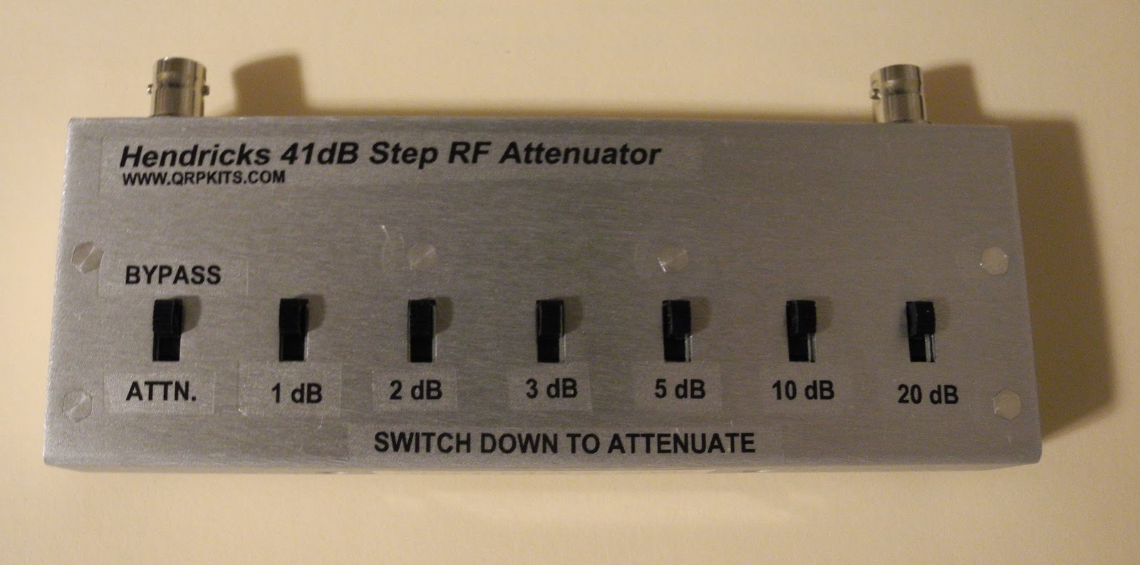
As we get into winter I'm starting to get back into some amateur radio projects. I recently built an RF attenuator kit  from Hendricks QRP Kits.

It's a nice simple attenuator that supports from 1 to 41 dB of attenuation with 50 ohm input and output impedance and can handle up to about 5 watts of power and is good to at least 30MHz. It's based on
a circuit in the ARRL Radio Amateur's Handbook.

Front View

Rear View
It only contains resistors and switches but comes with a nice silk-screened PCB and a metal case with decals for labelling the switches. It went together in an hour or so not counting the time spent waiting for the coats of Krylon clear coat finish to dry.

I plan to use it for a couple of applications. I have an RF signal generator built from a kit that has a fixed output. This will allow me to adjust the output level in 1 dB steps from 100% down to about .02% output level.

The other application, which it was designed primarily for, is to adjust the output level of a QRP transmitter so you can work at lower power levels with the flip of a few switches. The rear panel has a label which lists the percentage of output level and power output for 1W and 5W input) and various switch settings.

In may also come in handy when testing and calibrating ham radio and communications receivers.