Saturday, April 14, 2018

Rebuilding The Heathit AT-1 Transmitter - Testing and Wrapup


I did further testing of the restored unit, measuring voltages against the manual, and they all looked okay.

The unit was speced at operating from 105 to 125 VAC. At the time it was released line voltages in North America tended to be lower than today (typical 120 VAC or more now). For testing purposes I found that an input voltage of 117 VAC gave heater (6.3 VAC) and B+ voltages that were close to what was listed in the manual, so I did my testing with a Variac set to that level.

I measured the RF output on each band both with a rather inaccurate SWR/power meter and by measuring the peak to peak output voltage on an oscilloscope across a 50 Ohm dummy load.

    80M: 13 Watts
    40M: 12 Watts
    20M:6.3 Watts
    10M: 1 Watt

Power on 10 meter is quite low, but is apparently normal as the output tube has very low gain at the higher frequency. I captured the output on different bands on my oscilloscope:


Since the power supply is not regulated, there is quite a drop in the B+ on key down, from 512 to 430 volts. Note that there is also 139 VDC at the code key contacts, so you want to avoid touching them!

Here is the oscilloscope output of keying:


And using the spectrum analyzer mode of my Rigol scope:


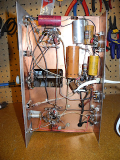
It is interesting compare some of circuitry before:


and after restoration:


This project was a lot of fun - I got to recreate the experience of building from a kit. I was also fascinating think that someone built this in the late 50s or early 60s and obviously used it quite heavily over the years.

I will have to try it on the air once I get an new antenna up. The power level qualifies it as a QRP rig.

I'm still looking to find the VF-1 matching VFO if I can get one at a reasonable price.

Wednesday, April 11, 2018

Rebuilding The Heathit AT-1 Transmitter - It's Alive!


Initial powerup tests are good and indicate that it is producing output on all four bands. I powered is up slowly with a Variac and then did some testing with an input voltage of about 110 VAC. I'm seeing output on all four bands, close to 10 Watts of output power depending on the band.


I find it is easier to adjust the driver and output controls by looking for maximum power output rather than the built in meter (the usual procedure is to adjust the driver control for a dip in the grid current and then adjust the output control for a peak in plate current - except for 80 meters where the drive
input is not tuned). The meter is an old iron vane type that is not damped and bounces all over the place until it stabilizes - which is not very good as you need to quickly adjust the controls to minimize the chances of damaging the output tube.


I still need to make some more voltage and power output measurements and look at the output waveform while keying.

I'm still also waiting for some octal plugs - one is used for an optional modulator (and needs to short two pins when not present) and one is for an optional VFO.


Heathkit sold the VF-1 VFO or Variable Frequency Oscillator that allowed it to transmitt at frequencies set by the VFO rather than fixed with crystals. I hope to acquire one of these some day - they show up on eBay quite often.


The unit could also transmit using AM voice, with an external modulator. Heathkit never offered a modulator kit, but various circuits were published at the time and in fact Heathkit published a suggested circuit in their 1955 sales flyer. It would make for an interesting project to build one - it used 5 tubes (one dual), making it a little more complex than the AT-1 transmitter.

Tuesday, April 10, 2018

Rebuilding The Heathit AT-1 Transmitter - Coil Wiring


The last stage of assembly is the wiring of the oscillator and bandswitch coils on the top of the chassis. Most of this is done with heavy solid wire. I used #14 solid copper house wire with the insulation removed. The oscillator coil, four bandswitch coils, two tuning capacitors, and bandswitches are all connected. It is important to follow the order shown in the manual and double check against making wiring errors that will be hard to change later during assembly.


Soldering the heavy wire is beyond the heat capacity of my small Weller soldering station. I dug out my old 140 Watt (also Weller) soldering gun and it was ideal for the job.


I am quite pleased with the results, expecially when comparing it to the photos I took of the original assembly. The last step is to connect the power cord.


I am now ready to power up and test the unit, after carefully checking the wiring one last time.

Monday, April 9, 2018

Rebuilding The Heathit AT-1 Transmitter - Final Amplifier Tube Wiring

I finished up the next set of assembly instructions  - the wiring around the final amplifier tube.


The last toroid is another large one that is too heavy to stand in the air by its leads. so I sat it on the chassis. As this has some high voltage (close to 1000 volts), I wrapped it in electrical tape to better insulate it from the chassis.


Next up is the assembly of the coils, much of which will use heavy bus wire and be on the top of the chassis.


Sunday, April 8, 2018

Rebuilding The Heathit AT-1 Transmitter - Oscillator Stage

I completed the wiring of the oscillator stage. The two RF chokes were replaced with toroids. Once is larger, so I mounted it against the chassis using a rubber grommet. The other is small enought to hang in the air by its leads.


I powered up the unit (slowly with a Variac) with the rectifier and oscillator tubes and a crystal installed and verified that I see an RF signal at the output of the stage, so it is working. Now to move on to the final amplifier stage.

Saturday, April 7, 2018

Rebuilding The Heathit AT-1 Transmitter - Power Supply Wiring

I finished up the first section of wiring assembly - the power supply.


I inserted the 5U4G tube, temporarily hooked it up to power, and slowly turned the voltage up using a Variac. I confirmed getting over 350 VDC from the power supply output, so the power supply is working,

Thursday, April 5, 2018

Rebuilding The Heathit AT-1 Transmitter - FT-243 Crystal Adaptor

While I was waiting for the tube sockets to arrive so I could get started with assembly, I took a little diversion.

The AT-1 has a socket to accept a crystal in the FT-243 form factor, which was popular at the time it was sold. Since then crystals have generally become smaller, and FT-243 crystals are no longer available. In fact, the demand for radio crystals has gone down significantly in recent years. One of the most well known crystal manufactuers for radio use, International Crystals, founded in 1951, shut down in 2017.

Some FT-243 type crystals are shown here, along with a more modern type meant to be soldered directly into a PCB.


As a little 3D printing project, I spent an evening using openSCAD to design a plastic case that allows a small crystal to be mounted inside, and using a couple of pins from an old octal vacuum tube for ins, turns it into the FT-243 form factor. Here is an example of my prototype.


I put the 3D printer model files here and made them freely available in case anyone else wants to use them.

Rebuilding The Heathit AT-1 Transmitter - Starting Assembly

Finally the tube sockets arrived, so I could get started with the actual assembly.


The new sockets were a little smaller than the originals and the mounting holes did not quite line up with the existing holes in the chassis. I cut the holes in the sockets into slots using a Dremel tool and cutoff wheel. That made it fit well enough.


As well as the tube sockets and terminal strips, I remounted the transformer and choke, front panel controls and panel.


I'm now ready to start wiring and installing the components.

Wednesday, April 4, 2018

Rebuilding The Heathit AT-1 Transmitter - Winding Inductors

As mentioned earlier, I will reuse the original band switch and oscillator coils, power transformer and filter choke. I decided to wind new RF chokes using toroidal cores.

It calls for two 1.1 mH chokes and one 90 uH. I used a little toroid design application I wrote myself and came up with these designs:

   1.1 mH: FT-82-43 core, 44 turns, #28 wire.
     90 uH: FT-50-43 core, 13 turns, #28 wire.


I wound them and measured the values using my AADE L/C meter. They read a little low so I added a few turns.


One other part I didn't mention earlier - I will replace the line cord with a new one using a brown two-wire extension cord that is similar to the original.

Tuesday, April 3, 2018

Rebuilding The Heathit AT-1 Transmitter - Painting the Chassis


The chassis was very corroded. It is steel plated with copper, and because the corrosion has come through the plating, sanding it will not restore it to as new because the copper is gone in some areas.

It could be replated with copper, but that is quite an effort to go to or an expense to have done commercially by a plating shop.


My solution was just to paint it. After some seartching I was able to find metallic (shiny) copper spray paint at a Michael's craft store. A lot of small coats were applied to the
top, bottom, and sides, until the finish was acceptable.


I also straightened it as it was a little bent (using a hammer protected by a towel).

The paint is not conductive, so I need to scrape it off wherever the tube sockets, terminal strips, and connectors connect to the chassis so that they make a good connection to ground. You can do this with a large drill bit turned by hand, and with a small file for the larger holes like those for the tube sockets.