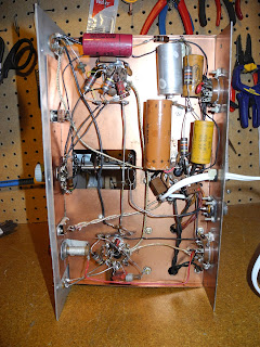
I did further testing of the restored unit, measuring voltages against the manual, and they all looked okay.
The unit was speced at operating from 105 to 125 VAC. At the time it was released line voltages in North America tended to be lower than today (typical 120 VAC or more now). For testing purposes I found that an input voltage of 117 VAC gave heater (6.3 VAC) and B+ voltages that were close to what was listed in the manual, so I did my testing with a Variac set to that level.
I measured the RF output on each band both with a rather inaccurate SWR/power meter and by measuring the peak to peak output voltage on an oscilloscope across a 50 Ohm dummy load.
80M: 13 Watts
40M: 12 Watts
20M:6.3 Watts
10M: 1 Watt
Power on 10 meter is quite low, but is apparently normal as the output tube has very low gain at the higher frequency. I captured the output on different bands on my oscilloscope:
Since the power supply is not regulated, there is quite a drop in the B+ on key down, from 512 to 430 volts. Note that there is also 139 VDC at the code key contacts, so you want to avoid touching them!
Here is the oscilloscope output of keying:
And using the spectrum analyzer mode of my Rigol scope:
It is interesting compare some of circuitry before:
and after restoration:
This project was a lot of fun - I got to recreate the experience of building from a kit. I was also fascinating think that someone built this in the late 50s or early 60s and obviously used it quite heavily over the years.
I will have to try it on the air once I get an new antenna up. The power level qualifies it as a QRP rig.
I'm still looking to find the VF-1 matching VFO if I can get one at a reasonable price.


1 comment:
Jeff, good job well done!
Post a Comment