Monday, April 2, 2018

Rebuilding The Heathit AT-1 Transmitter - Sources for New Parts

I researched and ordered the new parts I would need.


First was a new manual, as there were no complete manuals available on the Internet. I ordered a manual from The Manualman, a source I've used before and which offers very high quality spiral bound reproduction manuals. It arrived within a few days and was very clean and complete with foldout schematic and illustrations.


While I had a few of the necessary capacitors in hand, I ordered the rest from Just Radios. They stocked everything I needed, including the silver mica caps. The order also arrived in a couple of days.

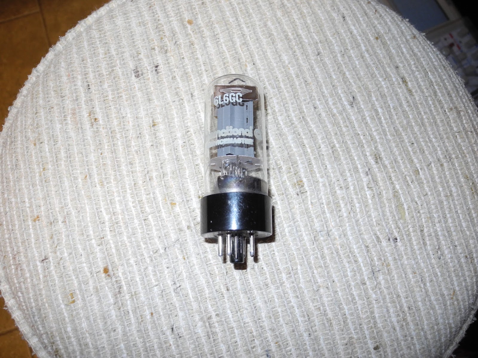
One item that took some research was the 6L6 tube. It is available, but can be expensive because it is also popular with tube-based electric guitar amplifier and hi-fi/stereo enthusiasts. The original metal 6L6 is harder to find than the glass 6L6GC. There seems to be no reason I can't use the 6L6GC and in fact it has better specs, so I opted to go with that. Being in Canada, shipping was quite high from some of the larger tube vendors. I ended up finding a NOS 6L6GC tube on eBay (from a seller in Germany). I have now received it.

Some more searching on eBay found sources for the octal tube sockets and plugs that I needed. These have been ordered but have not yet been received yet (they are coming from China).

I had all the needed resistors on hand.

I will use the original band coils and oscillator coils as they are unique to the AT-1, as well as the variable caps. It appeared that some of the RF chokes in my unit had been replaced with different values (and there were four rather than three -- one appeared to be added as a key click filter). I decided to wind replacements for these myself using toroidal core, which should perform well but not appear original.

I will also keep the power transformer and filter choke.


The terminal strips, jacks, switches, and other assorted hardware will be replaced or the existing ones used depending on condition of the original parts and what I have on hand.

Sunday, April 1, 2018

Rebuilding The Heathit AT-1 Transmitter - Teardown

I took a deep breath and totally tore the unit down to the bare metal chassis.


While doing so, I noticed a couple of capacitors with open leads - one power supply filter cap and one (large red) mica cap. I'm not sure if these were in this condition before I started the teardown.


I removed all wires and components from the terminal strips, switches, tube sockets as I will have to reuse some of them. The component leads were straightened and they were all set aside.

I kept all parts, although I'm not planning to reuse any of the fixed caps or resistors.

Saturday, March 31, 2018

Rebuilding The Heathit AT-1 Transmitter - Planning

To plan the AT-1 restoration, I collected information I could on the unit including a partial manual and some other articles published in the past on the radio and modifications for it.


I took many high resolution digital camera pictures from as many angles as possible to assist when I reassemble it.

I also made a spreadsheet of the parts list (bill of materials), based on the BOM in the manual, annotated with component designations (the original manual did not use any) and notes on whether to reuse the existing part or purchase new one, and the vendor to get the parts from, where applicable.


I took key voltage measurements as well as measuringe the RF power output, for later comparison when it is rebuilt. I get about 10 Watts of power on the lower bands, and 4 Watts on 10 meters.


I think I will keep the mod for the pilot lamp since there is a large hole in the chassis and front panel drilled for it and it isuseful to be able to see when it is powered on.

Friday, March 30, 2018

Rebuilding The Heathit AT-1 Transmitter - Overview


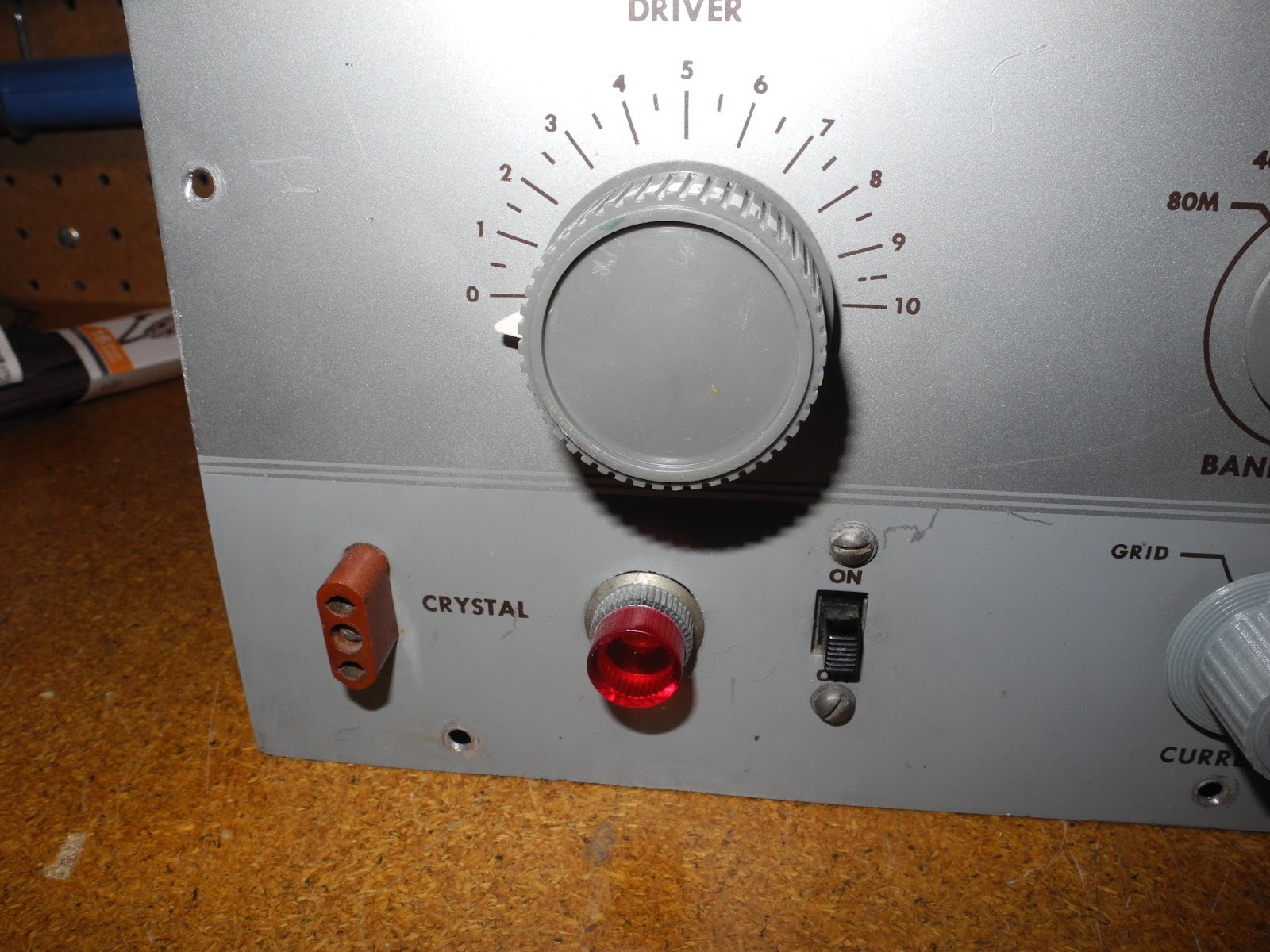
I decided to start a restoration project on this Heathkit AT-1 transmitter. This was Heathkit's first amateur radio kit, and was quite successful, with many built and used in the late 1950s and 60s and even today for fun and nostalgia reasons.

I bought this unit at a hamfest a few years ago and did some restoration to get it working, including painting the case. I made a YouTube video that describes it in detail.


Now I would like to more completely restore it. The copper plated chassis is badly corroded and the construction quality is poor. Many of these units were built by beginners, often young people with limited experience in electronics. No doubt many repairs and mods were also done to this unit in the over 50 years since it was first built. This one has had a modification done to replace the final tube with a 6E26 to get more output - it was described in an article in Popular Electronics magazine in 1958, as well as a few other mods.


My plan is to totally strip it down to the bare chassis, removing all components. Then I will rebuild it from scratch using some of the existing parts and new ones, where possible. I will also undo the mods and revert it back to the original circuit.


Not all parts will be original, so it won't be "museum quality". It is a tradeoff between keeping the original circuit but using new parts so it works as well or better than new. If I was planning to use on a regular basis, I would make some additional changes to make it a little safer: at minimum a grounded cord, fuse, and some safety caps.

A total rebuilt like this is sometimes done for collectable radios. The AT-1 is somewhat collectable, but not particularly valuable. I have always wanted to do a complete rebuild of a Heathkit, and this will be a lot less effort than for a more complex transceiver like a Heathkit HW-101, for example.

Part of the fun will be the opportunity to build a Heathkit from scratch by following the steps in the manual.

Tuesday, September 5, 2017

3D Printing Heathkit Knobs


I recently acquired a 3D printer, a LulzBot Mini. My son also has a Prusa Original i3. An interesting application for 3D printers is making replacement parts that are difficult or expensive to obtain. One that immediately came to my mind was knobs for Heathkit equipment.


My son did the first attempt at making one of the most common knobs used on the so-called Classic I style of Heathkit equipment, commonly used in test equipment and amateur radio gear. It came out quite well. I subsequently added models for the larger and smaller versions of these knobs, a version with two concentric knobs, and a pointer.


I used an open source CAD program called OpenSCAD which uses a scripting language that is easy to learn for most people with some programming experience. It works well for designs that can be mode up from primitive shapes like cylinders, cubes, etc.


I have a number of units of Heathkit test equipment that are missing the same carrying handle. It seems that people often removed the handles so they could stack the equipment. I also designed a replacement for the handle that works quite well. I replaced the handles on four units that I have.


I used a material called PLA, which is an inexpensive, strong, and non-toxic plastic. There are many different materials and colours to choose from. I used the highest quality, which isn't on par with the original knobs but I think it is completely acceptable for test equipment that you intend to use. I have a number of units that were missing some knobs, like the unit above which has two original knobs on the left and two 3D printed replacements on the right (as well as the handle).

The files are freely available on Thingiverse, one of the most popular 3D model sites. The original files are here at this github project. They are licensed under a Creative Commmons license. I hope to make some more designs in future.

Saturday, July 29, 2017

Heathkit Oscilloscopes

I recently picked up a Heathkit IO-10 oscilloscope which I will be restoring and then highlighting in a YouTube video.

A recent post to a Heathkit mailing list asked about a complete list of Heathkit oscilloscopes. My book Classic Heathkit Test Equipment has a chapter of oscilloscopes and includes scopes in a table of all of the Heathkit test equipment.

Here, taken from my book, is a list of all of the models of oscilloscopes I was able to identify through a number of sources. They are sorted by date of introduction. I was able to identify 67 unique models, made from 1947 to 1989.

Model Description First Year Comments
O-1 Oscilloscope 1947 5”
O-2 Oscilloscope 1948 5”
O-3 Oscilloscope 1948 5”, 150 kHz
O-4 Oscilloscope 1949 5”, 2 MHz
O-5 Oscilloscope 1950 5”, 2.2MHz
O-6 Oscilloscope 1950 5”, 200 kHz
O-7 Oscilloscope 1951 5”, 250 kHz
O-8 Oscilloscope 1951 5”, 2MHz
O-9 Oscilloscope 1951 5”, 3 MHz
O-10 Oscilloscope 1955 5”, 400 kHz, PC board
OL-1 Oscilloscope 1955 5”, 5 MHz
OM-1 Oscilloscope 1955 5”, 5 MHz
O-11 Oscilloscope 1957 5”, 5 MHz
OM-2 Oscilloscope 1957 5”
O-12 Oscilloscope 1958 5”, 5 MHz
OM-3 Oscilloscope 1958 5”, 1.2 MHz
OP-1 Oscilloscope 1958 2.2 MHz
OR-1 Oscilloscope 1959 5”, 200 kHz
IO-10 Oscilloscope 1960 3”, 200 kHz, recurrent sweep
IO-30 Oscilloscope 1960 5”, 5MHz
IO-21 Oscilloscope 1961 3”, 200 kHz
IO-12 Oscilloscope 1962 5”, 4MHz
EUW-25 Oscilloscope 1963 3”, 400 kHz
EV-3 Oscilloscope 1964 IMPScope biological EKG type
IO-14 Oscilloscope 1966 5”, 8MHz
EVW-3 Oscilloscope 1968 Assembled version of EV-3
IO-17 Oscilloscope 1968 3”, 5MHz
IO-18 Oscilloscope 1968 5”, 5MHz
EU-70 Oscilloscope 1970 15 MHz, dual trace, solid-state, assembled
IO-101 Vectorscope/Color Generator 1970 3” vectorscope and color bar/pattern generator
IO-102 Oscilloscope 1971 5”, 5MHz
IO-105 Oscilloscope 1971 5”, 15MHz, dual trace
IO-1128 Oscilloscope 1971 3”, vector monitor
IOW-18S Oscilloscope 1971 Berkeley Physics Laboratory, 5” laboratory
IO-103 Oscilloscope 1972 5”, 10MHz
SO-29 Oscilloscope 1972 Biological, high gain DC
IO-104 Oscilloscope 1973 5”, 15MHz
IO-4510 Oscilloscope 1974 5”, 15 MHz, dual trace
SO-4510 Oscilloscope 1974 Assembled version of IO-4510
IO-4530 Oscilloscope 1975 5”, 10 MHz, TV Service
IO-4540 Oscilloscope 1975 5”, 5 MHz, hobby/service
IO-4560 Oscilloscope 1975 5”, 5 MHz, auto triggered sweep
SO-4530 Oscilloscope 1975 Assembled version of IO-4530
SO-4540 Oscilloscope 1975 Assembled version of IO-4540
IO-4550 Oscilloscope 1976 5”, 10 MHz, dual trace
SO-4550 Oscilloscope 1976 Assembled version of IO-4550
IO-4101 Oscilloscope 1977 Vectorscope like IO-101
IO-4541 Oscilloscope 1977 5”, 5 MHz, special TV triggering
IO-4555 Oscilloscope 1978 5”, 10 MHz
IO-4105 Oscilloscope 1979 5”, 5MHz
IO-4205 Oscilloscope 1979 5”, 5MHz, dual trace
IO-4235 Oscilloscope 1979 5”, 35 MHz, dual trace, delayed sweep
SO-4105 Oscilloscope 1979 Assembled version of IO-4105
SO-4205 Oscilloscope 1979 Assembled version of IO-4205
IO-3220 Oscilloscope 1982 5”, 20MHz, dual trace, battery powered
SO-3220 Oscilloscope 1982 Assembled version of IO-3220
IO-4360 Oscilloscope 1984 5”, 60 MHz, triple trace
SO-4221 Oscilloscope 1987 5”, 20 MHz, dual trace
SO-4226 Oscilloscope 1987 5”, 25 MHz, dual trace
SO-4521 Oscilloscope 1987 5”, 50 MHz, dual trace
SDS-5000 Oscilloscope 1988 Computer-based
ID-4850 Digital Memory Oscilloscope 1989 Digital memory box for scopes
IO-4210 Oscilloscope 1989 5”, 10MHz, dual trace
IO-4225 Oscilloscope 1989 5”, 25 MHz, dual trace
SO-4552 Oscilloscope 1989 5”, 25 MHz
SO-4554 Oscilloscope 1989 5”, 40 MHz

Sunday, July 9, 2017

Building a 68000 Single Board Computer - 6809 to 68000 Assembly Language Source Translator

Unlike Intel, which made a decision to keep a high level of compatibility in their x86 processor line, from the 8086 through 286, 386, 486, and Pentium and beyond, Motorola made a clean break when they introduced the 68000. It didn't offer any software compatibility with their earlier processors like the 6800 and 6809.

However, Motorola offered a tool to help programmers port their source code from the 6809 to 68000 microprocessor. The tool, written in Pascal, was intended to do about 90% of the work of translation.

I was able to find a copy of this tool at http://www.retro.co.za/68000/XLATE09/ and try it out. It includes the tool (both executable and source code), documentation, and some sample files.

I was able to run the original trans09.com executable under using the dosbox MS-DOS emulator. I was also able to run it under Windows 10, but I got a number of errors that I had to ignore.

The tool was written in Pascal. It didn't specify which compiler it was targetted at, but it looks like pretty standard Pascal. I was able to compile it using the Free Pascal compiler under Linux with the addition of one line: "Uses Crt;". I made a few other changes to remove warnings about unused variables. The data files used by the program also needed to be renamed to lower case as Linux is case sensitive.

The tool ran quite well, working as described. Much of the translation rules are contained in data files which can be modified. It also uses some small routines which need to be assembled separately.

M6809 to M68000 Source Code Translator     Version 1.2
Systems Engg, E. Kilbride, Scotland
Motorola Inc. Copyright 1986

   Code in       Code out         Errors         Warnings
      17             23              0               4

The basic approach is to map the 6809 registers to corresponding 68000 registers, e.g. A to D0, B to D1, D to D2, X to A0, and Y to A1. It converts 6809 instructions to corresponding 68000 versions, e.g. LDA to MOVE, and points out possible problem areas, like where the behavior of the overflow flag may be different. Some instructions cannot be converted at all. The intention is that this might do about 90% of the conversion and a programmer would need to do the rest.

Here is a sample conversion, first the 6809 code:

* Sample input program
NULL     EQU   0
         CMPA  #9
         BLS   CB1HX1           branch if number is 0-9
         ADDA  #7               number is 10-15 so add 7 to make it A-F

CB1HX1   ADDA  #'0              add the ASCII offset
         RTS

OP1HEX   PSHS   A               save the binary number
         BSR    CB1HEX          convert the number to its ASCII equivalent
         LBSR   OPCHAR          and output it to the system terminal
         PULS   A,PC            restore the binary number and exit
         EXG    A,B             save the l.s. ASCII character in B; original 8-bit number to A
         LSRA                   shift the m.s. half byte into the l.s half byte
         LSRA
         LSRA
         LSRA
         NOP
         RTS                    leave the m.s. ASCII character in A

And now the resulting 68000 version generated by the tool:

*++       ******   STUB EXTERNAL REFERENCES  ******

                  XREF ..DIN,..DOUT,..JSR,..RTS,..CTOX,..CREP
                  XREF ..DPR,..DPW,..CLRAB,..MUL,..INIT,..VREP
          
* Sample input program
NULL      EQU 0                 
          CMP.B #9,D0           
          BLS CB1HX1            branch if number is 0-9
          ADD.B  #7,D0          number is 10-15 so add 7 to make it A-F

CB1HX1    ADD.B  #'0',D0        add the ASCII offset
          BSR ..RTS              

OP1HEX    MOVEM.L D0,-(A6)      save the binary number
          BSR CB1HEX            convert the number to its ASCII equivalent
          BSR OPCHAR            and output it to the system terminal
          MOVEM.L (A6)+,D0      restore the binary number and exit
          MOVE.L (A6)+,A3       
          JMP (A3)              
          EXG.L  D0,D1          save the l.s. ASCII character in B; original 8-
*                               bit number to A
          LSR.B #1,D0           shift the m.s. half byte into the l.s half byte
** WARNING **                      * V-BIT CLEARED *
          LSR.B #1,D0            
** WARNING **                      * V-BIT CLEARED *
          LSR.B #1,D0            
** WARNING **                      * V-BIT CLEARED *
          LSR.B #1,D0            
** WARNING **                      * V-BIT CLEARED *
          NOP                    
          BSR ..RTS             leave the m.s. ASCII character in A

To actually use this tool you may need to modify it and/or the data files to work with your particular 68000 cross-assembler. For example, the VASM assembler I use does not like the stub routine names starting with two dots like "..RTS" but will accept them with only one dot (e.g. ".RTS").

I've put my test files and notes here: https://github.com/jefftranter/68000/tree/master/xlate09

I don't know if anyone used this tool to port any significant programs for the 6809 to 68000, but it is a rather interesting tool and the concept could be applicable to other processors. It is also an alternative approach to emulation, which is often use but has a different set of tradeoffs (like performance).