Showing posts with label 6522. Show all posts

Saturday, March 24, 2012

6522 VIA Experiment #6

In this last instalment of my series on the 6522 VIA we'll use a little more hardware to show how to generate analog waveforms using a simple digital to analog converter.


You can read all about the theory of digital to analog conversion elsewhere (such as here ). In our example we'll use a simple digital analog converter called a resistor ladder, specifically an R-2R ladder.

All we need is some resistors connected to the digital output pins of one of the 6522 VIA ports. With 8 pins we could make an 8-bit D/A converter, or even a 16-but using both ports, but to simplify the circuit I'll just use a 4-bit ladder. That will require 8 resistors. The basic circuit is shown below.

4 Bit Resistor Ladder
With 4 bits we have 2^4 or 16 possible output values. The analog voltage from the D/A converter is proportional to the value we write, ranging from 0 to 5 volts as we write the values 0 through 15.

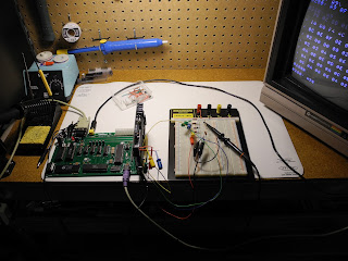
I chose to use R = 10K (or 10,000 ohms). I used standard resistor values of 12K and 20K for R and 2R. The four low order pins of the 6522 VIA port A are used. It was quickly wired up on solderless breadboard.
Resistor Ladder Circuit on Breadboard
The code is very simple. We need to set the appropriate pins as output. We repeatedly write out samples from a table in memory. I chose to use a table with 16 samples. We simply loop, writing subsequent table values to the port and repeat when we get to the end of the table.

We can generate various waveforms depending on the values in the table. I chose three common ones. A ramp is a waveform that increases linearly from zero to the maximum value and then repeats. With 16 data samples we simply use the values from 0 to 15. A triangle increases linearly from a minimum value to a maximum value and then decreases linearly back to the minimum. The data samples for this were trivial to choose.

A sine wave is a little trickier. We want to use values corresponding to a sine curve, but we need to scale them to the range of data we have (0 to 15) and round them to integer values. To do this I calculated the values in a spreadsheet. Here are the values in my spreadsheet:

Sample Value        Rounded
0 7.5        7
1 10.3701257427 10
2 12.8033008589 12
3 14.4290964938 14
4 15        15
5 14.4290964938 14
6 12.8033008589 12
7 10.3701257427 10
8 7.5        7
9 4.6298742573 4
10 2.1966991411 2
11 0.5709035062 0
12 0        0
13 0.5709035062 0
14 2.1966991411 2
15 4.6298742573 4

The formula for the values was 7.5*SIN(2*PI() * n/16) + 15/2 where n is the sample number. The rounded values are the integer value of these (i.e. the INT() function).

Here is the entire code:
   
       .include "6522.inc"
       SAMPLES = 16    ; Number of samples in table
       LDA #001111  ; Set low 4 bits of port A to all outputs
       STA DDRA
START: 
       LDX #0
LOOP:
       LDA SINE,X      ; Get value. Select SINE, RAMP, or TRIANGLE
       STA PORTA       ; Write to port
       NOP             ; Can add more NOPS to slow down frequency
       INX             ; increment index
       CPX #SAMPLES    ; are we at end?
       BNE LOOP        ; if not, continue
       JMP START       ; otherwise restart
; Sine values calculated using spreadsheet
SINE:
       .byte 7,10,12,14,15,14,12,10,7,4,2,0,0,0,2,4
RAMP:
       .byte 0,1,2,3,4,5,6,7,8,9,10,11,12,13,14,15
TRIANGLE:
       .byte 0,2,4,6,8,10,12,14,15,14,12,10,8,6,4,2

You can select which waveform to generate by changing the line

       LDA SINE,X      ; Get value. Select SINE, RAMP, or TRIANGLE

to use the appropriate table.

With a 2MHz CPU clock I measured a sine wave of 7.245 KHz. Below you can see the three waveforms displayed on an oscilloscope.
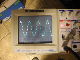
Sine Wave

Ramp Wave

Triangle Wave

How could we extend this further? With more D/A bits we could generate more accurate waveforms. 8-bits is pretty good. CD audio uses 16-bits, which we could do with both VIA ports but we likely couldn't get it running at the 44KHz rate that CD audio uses and we'd quickly run out of memory to store the samples.

You can imagine using this scheme for generating simple sounds. To drive a real device you'd want to add some buffering using an Op Amp or similar. You could then drive amplified speakers, for example.

The code takes all the CPU resources. It could be made interrupt driven, as in the previous article in this series. However, any significant sample rate would take a lot of CPU resources even if run interrupt driven.


I hope you enjoyed this series on the 6522 VIA. There are other features of the 6522 VIA chip, such as the shift register, that we did not explore. I encourage you to study the data sheet and see what applications you can come up with.

I appreciate any feedback on this series and I'd like to hear if you tried any of these experiments yourself.

The source code and Woz monitor binaries for this series can all be found here.
Friday, March 23, 2012

6522 VIA Experiment #5

In this experiment we will play with interrupts and show how to implement a time of day clock using the 6522 VIA.

Interrupts are a feature of most microprocessors that allows the normal flow of execution to be, well, interrupted. It is normally triggered by a hardware line.

Rather than delve into interrupts in detail I refer you to the 6502 data sheet as well as this good tutorial .

The timers on the 6522 can generate interrupts when a timer counts down to zero. In our example we'll implement a time of day clock by having the timer regularly generate interrupts, and incrementing memory locations in the interrupt service routine to track the time of day.

Because this is entirely interrupt driven, it won't (or shouldn't) affect programs running on the machine if they don't disable interrupts or conflict with the memory locations we use.

There will be two parts to our code:
  1. The code to set up the timer and interrupt service routine.
  2. The interrupt service routine itself.

The set up routine needs to first disable interrupts while we set things up. The interrupt vector (address) on the Replica 1 is $0100, which is in RAM. We want to point this to our own code, so we write a JMP instruction there to transfer control to our interrupt routine.

I decided to run the timer to generate interrupts every 100th of a second (a time interval sometimes called a jiffy). We'll need a memory location to count the number of jiffies. We'll also count seconds, minutes, and hours. Each of these can fit in an 8-bit memory location.

To set up the 6522 VIA, we enable interrupts from timer 1 in the Interrupt Enable Register. We set timer 1 to continuous mode with the PB7 output disabled. Now we can re-enable interrupts on the processor. We write the low and high bytes of the timer with the value that corresponds to a 1/100th of a second, which starts the timer. Now, whenever the timer counts down to zero it will generate an interrupt on the IRQ line of the 6522 chip which is wired to the IRQ line on the 6502.

Our interrupt routine needs to do the following:
  1. First save on the stack any registers we will be using so we can restore them. In our case only the accumulator.
  2. Read the Timer 1 low byte. This clears the interrupt.
  3. Now we increment the jiffies count. If we reach 100 we want to roll it over to zero and add one to the minutes If the minutes were incremented, we check if they reached 60. If so, we roll them over to zero and increment the hours count.
  4. Similarly we check if hours reached 24, in which case it rolls over to zero.
  5. When done we restore the accumulator from the stack and return. Note that we use an RTI (Return From Interrupt) instruction and not RTS for this.

For debug purposes I added code that will write the characters "S", "M", and "H" when the seconds, minutes, and hours are incremented. You can comment out this code when not testing the software. The complete code is below.

 .include "6522.inc"

    ECHO     = $FFEF    ; Woz monitor
    COUNT    = 19998    ; 100 Hz sample rate (10 msec interrupts) assuming 2 MHz CPU clock
    IRQ      = $0100    ; IRQ vector

    JIFFIES  = $0403    ; 100ths of seconds
    SECONDS  = $0402    ; counts seconds
    MINUTES  = $0401    ; counts minutes
    HOURS    = $0400    ; counts hours

    SEI                 ; mask interrupts
    LDA #$4C            ; JMP ISR instruction
    STA IRQ             ; Store at interrupt vector
    LDA #<ISR
    STA IRQ+1
    LDA #>ISR
    STA IRQ+2

    LDA #0              ; Set clock to zero
    STA JIFFIES
    STA SECONDS
    STA MINUTES
    STA HOURS

    LDA #%11000000
    STA IER             ; enable T1 interrupts
        
    LDA #%01000000
    STA ACR             ; T1 continuous, PB7 disabled

    CLI                 ; enable interrupts

    LDA #<COUNT
    STA T1CL            ; Set low byte of count
    LDA #>COUNT
    STA T1CH            ; Set high byte of count
    RTS                 ; Done

; Interrupt service routine
ISR:
    PHA                 ; save A

    BIT T1CL            ; Clears interrupt

    LDA JIFFIES
    CLC
    ADC #1
    STA JIFFIES
    CMP #100            ; reached 1 second?
    BNE DONE            ; if not, done for now

    LDA #'S'            ; for test purposes
    JSR ECHO

    LDA #0              ; reset jiffies
    STA JIFFIES
    LDA SECONDS         ; increment seconds
    CLC
    ADC #1
    STA SECONDS
    CMP #60             ; reached 1 minute?
    BNE DONE            ; if not, done for now

    LDA #'M'            ; for test purposes
    JSR ECHO

    LDA #0              ; reset seconds
    STA SECONDS
    LDA MINUTES         ; increment minutes
    CLC
    ADC #1
    STA MINUTES
    CMP #60             ; reached 1 hour?
    BNE DONE            ; if not, done for now
        
    LDA #'H'            ; for test purposes
    JSR ECHO

    LDA #0              ; reset minutes
    STA MINUTES
    LDA HOURS           ; increment hours
    CLC
    ADC #1
    STA HOURS
    CMP #24             ; reached 24 hours?
    BNE DONE            ; if not, done for now

    LDA #0              ; reset hours
    STA HOURS

DONE:
    PLA                 ; restore A
    RTI                 ; and return

When run, it sets up the interrupt handler and then returns to the Woz monitor. You can examine the time of day values by dumping memory in the Woz monitor, e.g.

  401.404

and see the locations that store the hours, minutes, seconds, and jiffies. Do it a few times to satisfy yourself that it is counting. If you want you can manually write the current time in hours minutes and seconds to set the clock to the correct time. I ran it overnight and it was still within one second of the correct time.

Here is a picture of the IRQ line on an oscilloscope showing the regularly spaced pulses every 10 milliseconds.

Scope Probe on Pin 4 (IRQ) of the 6502

100msec Interrupts from the 6522
If you left in the debug code you should also see "S", "M", and "H" characters appearing (which is a little annoying when you are using the Woz monitor).

It's fortunate that the interrupt vector in the Replica 1 points to RAM, as it lets us put our handler routine there. The vector for NMI also points to RAM but the NMI line is not connected to any devices. The reset vector points to ROM, the Woz Monitor, as it should.

Unfortunately $0100 is not a great choice as on the 6502 the stack sits in page 1 of memory. There is a chance that the JMP to our interrupt handler will get corrupted if the stack pointer reaches that location and data pushed on the stack writes over it. We could improve our example program by initializing the stack pointer to somewhere away from $0100 to reduce the chances of this but it could still happen. If you want to make use of interrupts on the Replica 1 you should probably reprogram your EEPROM to point the IRQ vector somewhere else.

To show that the clock routine runs independently of the main code executing on the processor, we can run BASIC and still access the time of day. Here is a simple BASIC program that shows the time of day by PEEKing the appropriate memory locations.

LOMEM=1100 : REM TO MAKE SURE WE DON'T WRITE OVER OUR ISR
10 H=PEEK (1024) : REM $0400
20 M=PEEK (1025) : REM $0401
30 S=PEEK (1026) : REM $0402
40 PRINT H;":";M;":";S
50 IF PEEK (1026)=S THEN 50 : WAIT FOR SECONDS TO CHANGE
60 GOTO 10

Typical output looks like the screen below:

Output of BASIC Program Showing Time
Are there any limitations of our little real time clock? Well, yes. We only count time. You could easily imagine extending it to track the day, month, and year. The time gets lost if the system is powered down or even reset (this stops the timer on the VIA). If any software disables interrupts, we will stop counting time during that period. If there are interrupts from other devices, our code doesn't handle that. Finally, there is the possible stack corruption issue described earlier.

There are dedicated hardware real-time clock (RTC) chips that do a better job, but of course they aren't free.

6522 VIA Experiment #4

This time we're going to extend the pulse counting example from the last instalment to be able to measure frequency. The code is short but a little complex.

To measure frequency we need to count pulses over a known period of time. We saw how Timer 2 can count pulses. We can also use Timer 1 to count a period of time for us.

We'll use Timer 2 in the same pulse counting mode as before where it counts transitions on line PB6. We'll put Timer 1 in the single shot mode where it counts down to zero from a known value at the system clock rate.

We'll count the number of pulses we see over this period of time and display it. Then we'll repeat forever. This is essentially what a device called a digital frequency counter does.

We poll the timer to see when it reaches zero. This is not very efficient and a nice enhancement would be to make this interrupt driven but we want to keep it simple for now. We will look at an interrupt driven example later in this series.

Ideally we would like to convert the result to an actual frequency. To do that we need to divide the number of pulses by the time period (i.e. to get cycles per second or Hertz). If we did this, a good sample rate might be one that is one over a multiple of 2, e.g. 1/16, 1/32, or 1/64 of a second since we can do this calculation by shifting the data by a number of bits rather than doing a full divide operation. For this example I used a 20 Hertz sample rate and didn't calculate the frequency. I used the one's complement trick described in the last experiment to convert the count down to a count up.

The hardware setup here is a little messy. We need a source of pulses, i.e. a square wave at the appropriate TTL (5V) level. Initially I used the calibrate output of my oscilloscope as it puts out 2 volts peak to peak at around 1 KHz. This worked well enough to confirm that I got the right results.

I then used an audio oscillator (an old EICO model 377) to give me a source that I could vary in frequency. I set it to square wave output and then drove it through a 74LS04 inverter chip. I was concerned about possibly damaging the VIA chip if I inadvertently set the output voltage too high. This way I only risked damaging an inexpensive IC from my junk box.

You can see the setup below.

EICO Signal Generator
Breadboarded Circuit with 74LS04 Chip

The source code is below. Based on the information above and the comments in the code is should be self-explanatory.

 .include "6522.inc"

    ECHO     = $FFEF    ; Woz monitor
    PRBYTE   = $FFDC    ; Woz monitor
    CR       = $0D      ; Carriage return
    COUNT    = 49998    ; 20 Hz sample rate

    LDA #$00
    STA IER             ; disable all interrupts

    LDA #%00100000
    STA ACR             ; T1 single shot PB7 disabled, T2 pulse count mode

LOOP:
    LDA #
    STA T1CL            ; Set low byte of count
    LDA #>COUNT
    STA T1CH            ; Set high byte of count

    LDA #$FF            ; Set count for T2
    STA T2CL            ; Set low byte of count
    LDA #$FF
    STA T2CH            ; Set high byte of count

WAIT:
    LDA T1CH            ; wait for timer T1 to count down to zero
    BNE WAIT
    LDA T1CL
    BNE WAIT

    LDA T2CH            ; get high byte of T2 count
    EOR #$FF            ; take 1's complement
    JSR PRBYTE          ; print it
    LDA T2CL            ; get low byte of T2 count
    EOR #$FF            ; take 1's complement
    JSR PRBYTE          ; print it
    LDA #CR
    JSR ECHO            ; print newline
    JMP LOOP            ; repeat forever

As one example (the one shown on the display in the picture below), the input was at about 100KHz. I counted about $13AE pulses, or 5038 decimal. I used a 20 Hz sampling rate. 5038 * 20 Hz = 10,076 Hz. So my reading looks about right.

Signal Generator Output on Oscilloscope

Output of Program

My signal generator only went up to about 200KHz and I was able to measure this frequency.

You can imagine building a digital frequency counter using a 6502 and a VIA chip. In fact some modern counters a simple processor (e.g. a PIC) and some kind of display and not much more.

Thursday, March 22, 2012

6522 VIA Experiment #3

Up to now we've been playing with output so let's look at an example that uses input. Any lines of the 2 8-bit VIA ports can set as inputs and the value of the input (high or low) read from the output register. Timer 2 has an interesting mode - it can count pulses on line PB6. Once set up it will count pulses and update the timer registers, counting down. You can even have it generate an interrupt when the counter reaches zero.


For our example let's count pulses on the input. To do that we need a little hardware: a pullup resistor to +5V to keep the line high and a push button to ground to drive it low when pressed. The timer counts a pulse each time the PB6 line goes from high to low.

Below is our program. We set up the VIA not to generate any interrupts and set T2 to pulse counting mode. We initially set the timer to the maximum possible count, $FFFF. Then we start reading the low order count register to see when it changes. When it does, we display the upper and lower counter values.

Now the counter counts down. We really want to count pulses, counting up. If we want to convert this count down to a count up we can use a little trick. If we take the 1's complement (i.e. flip all the bits) we will get an increasing count. For example, here are the first four numbers counting down from $FFFF:

       Value                    1's Complement
 Hex        Binary             Binary         Hex
$FFFF  %1111111111111111  00000000000000  $0000
$FFFE  %1111111111111110  00000000000001  $0001
$FFFD  %1111111111111101  00000000000010  $0002

To take the 1's complement we can use the EOR (Exclusive OR) instruction with a value of all ones (i.e. $FF).

Here is the complete code.

       .include "6522.inc"


        ECHO    = $FFEF     ; Woz monitor
        PRBYTE  = $FFDC     ; Woz monitor


        CR      = $0D       ; Carriage return


        LDA #$00
        STA IER             ; disable all interrupts
        LDA #100000
        STA ACR             ; Set to T2 pulse count mode
        LDA #$FF
        STA T2CL            ; Set low byte of count
        LDA #$FF
        STA T2CH            ; Set high byte of count
        CLC
        LDA #CR
        JSR ECHO            ; print newline
LOOP:
        LDA T2CL
SAME:
        CMP T2CL            ; wait for LSB to change
        BEQ SAME
        LDA T2CH            ; get high byte of count
        EOR #$FF            ; complement the bits
        JSR PRBYTE          ; print it
        LDA T2CL            ; get low byte of count
        EOR #$FF            ; complement the bits
        JSR PRBYTE          ; print it
        LDA #CR
        JSR ECHO            ; print newline
        BCC LOOP            ; forever

The picture below shows our switch and pullup resistor on a breadboard wired to PB6.


Hardware Setup for Pulse Counting Experiment

Closeup of Switch and Pullup Resistor

And here we see the output counting down as the button is pressed repeatedly. I took this picture with an earlier version of the program that didn't convert the value to an increasing count so it is actually counting down here.

Program Output
In the next instalment we'll extend this idea of counting pulses to measure frequency.

6522 VIA Experiment #2

In this instalment we'll use the timer on the VIA to generate pulses.


The 6522 VIA has two timers. Timer 1 can operate in several modes. One of the modes is a free running mode where the PB7 line toggles every time the timer counts down to zero. In free running mode the timer continuously reloads the count when it reaches zero. This allows generating a square wave of an accurate frequency, with no CPU overhead once it is set up.

The frequency, f, of the output is determined by the formula:

        f = PH2 / (2 * (n + 2) )

where PH2 is the frequency of the phase 2 (CPU) clock and n is the timer count value. The maximum frequency is when n = 0, giving a frequency of 1/4 of the PH2 clock. On my system the clock is 2MHz (a stock Replica 1 is 1 MHz), giving a maximum frequency of 500 KHz. The minimum frequency is when n = hex $FFFF or 65535 decimal, resulting in a rate of about 15.26 Hz.

If you wanted a rate of 60 Hz for example, the closest timer value would be 16665 which results in a rate of 59.9988 Hz. Unfortunately, if you were to use this for a clock based on 60Hz, it would result in an error of more than one minute per day. It is better to use a time value that results in an exact multiple of seconds. For example, the value 9998 produces exactly 100 Hz.

The following BASIC program will show the timer values that give exact frequencies (you need to run it with an floating point BASIC like Applesoft Lite and not Integer BASIC).

REM BASIC program to find counts that result in exact frequencies
100  FOR I = 0 TO 65535
110  F = 1000000 / (I + 2)
120  IF F =  INT (F) THEN  PRINT I;" ";F
130  NEXT I

Here is the output of the program:

COUNT FREQ (HZ)
0 500000
2 250000
3 200000
6 125000
8 100000
14 62500
18 50000
23 40000
30 31250
38 25000
48 20000
62 15625
78 12500
98 10000
123 8000
158 6250
198 5000
248 4000
318 3125
398 2500
498 2000
623 1600
798 1250
998 1000
1248 800
1598 625
1998 500
2498 400
3123 320
3998 250
4998 200
6248 160
7998 125
9998 100
12498 80
15623 64
19998 50
24998 40
31248 32
39998 25
49998 20
62498 16

Now for the the code for our example. We first set the Interrupt Enable Register to not generate any interrupts as our code is not prepared to handle interrupts. We write to the ACR to set the Timer 1 mode. We then write the low and high bytes of the counter. Writing the high byte starts the counter counting. After that we return. At this point the VIA continues to generate square wave pulses on the PB7 output.

Here is the source code:

  .include "6522.inc"


  COUNT = $4119
      
  LDA #$00
  STA IER             ; disable all interrupts
  LDA #%11000000
  STA ACR             ; Set to T1 free running PB7 enabled
  LDA #<COUNT
  STA T1CL            ; Low byte of count
  LDA #>COUNT
  STA T1CH            ; High byte of count
  RTS

And here is the output on an oscilloscope. Mine scope has a counter this reports the frequency, quite close to the 60Hz we were aiming for.

60Hz Square Wave Output