Monday, December 31, 2012

Grab Bag: Raspberry Pi Case and App Store


I was ordering some electronic parts from Jameco recently and I notice they now carry an inexpensive Raspberry Pi case, so I ordered one. The case is made by Bud Industries. It is a simple design with only two (identical) plastic pieces that go together. It's a little big, but has the benefit of allowing lots of ventilation and it will probably have room for some of the available expansion boards or a ribbon cable connector to the GPIO pins.


Raspberry Pi Case
Recently I was digging through my junk box looking for a specific chip and realized I don't have very many TTL chips. I like electronics grab bags, and Jameco sells a number of different ones, so I also picked up their 100 Piece TTL Semiconductor Grab Bag. I just started sorting them but it looks like I got quite a good assortment of devices. They say it can contain surface mount parts as well as through hole but my grab bag only included DIP packages, which is great.

100 TTL Chips
The Raspberry Pi foundation recently opened an application store, for both paid and free apps. So I ported a small text adventure game that I wrote in C, originally for my Apple 1 replica, and packaged it for the Raspberry Pi store. It is a free download and you can get it from here.  I think the game is quite challenging and I encourage you to try it out if you have a Raspberry Pi. I'm also working on a graphical version that will use the Qt toolkit.

Friday, December 28, 2012

SB-310 Heathkit Catalog Listing

Here are scans of the listing for the SB-310 shortwave receiver from the 1971 US Heathkit catalogue. It was sold from 1967 to 1972 when it was replaced by the solid state SB-313. It originally came with a copy of the World Radio TV handbook shown here. The ashtray and pipe were not included :-)


SB-310 Receiver Gets A Speaker

I was able to get a matching SB-600 speaker on eBay for my SB-310 shortwave receiver. It has some paint chips but is not too bad looking overall. Probably thousands of these speakers were sold by Heathkit for the matching SB and HW series radios from 1966 through 1975, retailing for US$17.95 They tend to go for quite a high price on eBay. I got mine for a good price - probably because the seller listed it as an "SP-600" rather than an "SB-600" so many potential buyers may have missed it in searches.

SB-310 and SB-600 Speaker
The restoration of this radio only consisted of putting on a new line cord, cleaning it, and touching up the alignment. I made some rubber feet using rubber stoppers cut to size and drilled for a screw. I initially thought it was missing the 100 KHz crystal but it was installed in the LSB crystal socket (which is normally empty) by mistake.
Another View of the SB-310 Receiver
It is a good performer, picking up lots of shortwave stations in the evenings. The dial is linear and very accurate.

Repaired Function Switch With Microswitch
I was also able to fix the main issue with my SB-310, the broken power switch. It is a combined rotary wafer switch and power switch on the FUNCTION switch. Getting a new switch is almost impossible. I was able to rig up a micro switch in such a way as to be controlled by the rotor of the function switch. Provided that the Gorrilla glue holding the switch stays in place, it should do the job.

Tuesday, December 18, 2012

Raspberry Pi Radiation Monitor


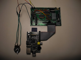
Some time ago built this Geiger counter kit. Details are in this Youtube video. I originally hooked it up via a serial port to a Linux desktop system running an Apache web server and wrote a simple shell script that displayed the current radiation level. Recently I moved it over to a Raspberry Pi.

The serial port uses the AdaFruit FTDI friend to convert the 3.3V level serial port on the Geiger counter to a USB serial device.

My son recently wrote some Python code to generate a nicer looking web page that includes a graph.
It uses the RGraph library.

I then made a little C program that reads the radiation data from the serial port, and writes it out in CSV format so it can be easily parsed by the Python code that generates the graphs. A cron job updates the web page every hour with the latest data.

Here is a picture of the hardware setup using a Raspberry Pi as the attached computer which is running the Apache web server:


And here is a closer shot of the Geiger counter:


Here is an image of a typical web page:


And here are some items that I use for testing the Geiger counter that are slightly radioactive: a couple of buttons made from glass that is coloured with Uranium:


If the system is active and I am not otherwise using the Raspberry Pi for something else, you can see the graph at this URL.

Sunday, December 16, 2012

A Small Collection of Digital Multimeters


I realized I have a small collection of DMMs (Digital MultiMeters) around that I have collected over the years. At one time most of these have been my primary meter for electronic work.


Left to right, we have a low cost non-autoranging model branded for Canadian Tire, followed by a newer auto-range but still low cost Canadian Tire branded model.

Then an early 1980s vintage Heathkit unit I bought at a garage sale, followed by a good quality Extech unit which is my current meter of choice, and finally a very small and low cost DMM I bought earlier this year that is handy to have around the bench to make quick measurements.

Sunday, December 2, 2012

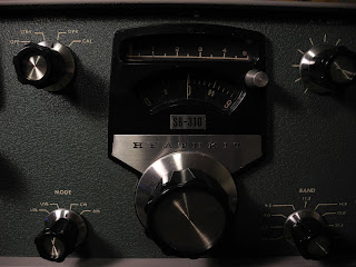
Heathkit SB-310 Shortwave Receiver


I recently purchased a Heathkit SB-310 shortwave receiver on Ebay and am restoring it. The SB-310 was Heathkit's top of the line shortwave receiver, based on the SB-300 Amateur Radio receiver.


It is an all tube receiver that was sold as a kit from  1967 to 1972 retailing at US$267.95. It covers nine shortwave bands which over most of the shortwave, amateur radio, and CB radio bands.


It has a very accurate and linear dial which used the heathkit LMO (Linear Master Oscillator) which was pre-assembled and aligned.


I post more details here later on the work to restore it, which was not much as the unit I purchased was working and very clean when I received it.

Wednesday, November 21, 2012

Arduino and GertBoard


The Arduino compatible microcontroller on the GertBoard is a nice feature that allows you to run most Arduino programs or "sketches" as they are called. They are written in a simplified subset of the C/C++ programming language. The Arduino chip has on-board digital and analog input/output pins and is more suited to real-time control than the Raspberry Pi which is running Linux, because you have full control of the chip for running your code. Under Linux, many processes are typically running and can preempt your device control program. The Arduino programs reside in flash memory so they are non-volatile and they start up in a fraction of a second from power on. The main limitations of the Arduino are that it can only run small programs, a few kilobytes in size, and it doesn't have a full operating system with features like a complete file system.

The work is all done by an Atmel ATmega 328 chip running at 12MHz. A special version of the "avrdude" program is available which allows the chip to be programmed from the Raspberry Pi's SPI bus on the GPIO port. The Arduino IDE, which runs fine on the Raspberry Pi, can then compile and upload programs to the Atmega chip.

Raspberry Pi and GertBoard

It provides 14 digital and 6 analog input/output pins. I ran several Arduino sketches which exercised the analog and digital inputs and outputs as well as the serial port. Remember these are in addition to the input/output ports of the GertBoard itself.

The Atmega chip on the GertBoard should be compatible with many Arduino programs but it is not directly compatible with Arduino shields (add-on boards) because it has a different hardware form factor, and it runs at 3.3V levels rather than the 5V logic of standard Arduinos.

Now, with all these capabilities, I have to think of a good hardware project.

Sunday, November 18, 2012

Testing The GertBoard


I was in Berlin, Germany this week to attend the Qt Developer Days conference Europe where I gave a talk on Qt and Raspberry Pi. I'll be giving the same talk at Qt Developer Days North America in Santa Clara, California from December 5 to 7, 2012.

Now that I am back home the the GertBoard has been assembled and is confirmed to be working.

Assembled GertBoard

I ran the included programs that exercise the pushbuttons, LEDs, open collectot drivers, PWM motor controller, A/D converter, and D/A converter.

Setup For Testing Motor Control
 Next up is to try the Arduino compatible microcontroller. I hope to make some videos of some programs running and post them on YouTube.

Testing the GertBoard and Raspberry Pi on the Bench

Friday, November 9, 2012

GertBoard Assembled

Soldering of the GertBoard kit took an evening, taking my time and examining all parts and solder joints carefully. I found the SMT parts were quite easy to solder -- my only worry was that I would lose some of them!

Assembled GertBoard (less ICs)

I've now completed the assembly and just have to insert the ICs before being ready to give it the initial "smoke test". Unfortunately it will have to wait a week until I am back from the Qt Developer Days conference in Germany where, among other things, I will be giving a presentation on Qt and the Raspberry Pi.

Thursday, November 8, 2012

GertBoard Kit Arrived


After several months of waiting I finally received my GertBoard kit. The GertBoard is an input/output expansion board for the Raspberry Pi.

Parts Included In GertBoard Kit

PCB Before Installing Components
It is shipped as a kit, although this is likely to change soon. It requires a significant number of parts, including some surface mount parts, so it is somewhat challenging to assemble.

So far I have reviewed the assembly instructions and confirmed that I have all the parts. In preparation, I did some practice soldering of some surface mount parts on some bare PCB. That went well so I am ready to start assembly.

SMT Soldering Practice

I'll post more here on my progress.

RF Attenuator Kit

As we get into winter I'm starting to get back into some amateur radio projects. I recently built an RF attenuator kit  from Hendricks QRP Kits.

It's a nice simple attenuator that supports from 1 to 41 dB of attenuation with 50 ohm input and output impedance and can handle up to about 5 watts of power and is good to at least 30MHz. It's based on
a circuit in the ARRL Radio Amateur's Handbook.

Front View

Rear View
It only contains resistors and switches but comes with a nice silk-screened PCB and a metal case with decals for labelling the switches. It went together in an hour or so not counting the time spent waiting for the coats of Krylon clear coat finish to dry.

I plan to use it for a couple of applications. I have an RF signal generator built from a kit that has a fixed output. This will allow me to adjust the output level in 1 dB steps from 100% down to about .02% output level.

The other application, which it was designed primarily for, is to adjust the output level of a QRP transmitter so you can work at lower power levels with the flip of a few switches. The rear panel has a label which lists the percentage of output level and power output for 1W and 5W input) and various switch settings.

In may also come in handy when testing and calibrating ham radio and communications receivers.

Saturday, October 6, 2012

The Apple 1 Cassette Interface


The Apple Cassette Interface (ACI) was the only accessory sold for the Apple 1 computer. It allowed saving and loading programs from cassette tape using an inexpensive tape recorder.

Vince Briel  recently made a batch of replica ACI boards both as kits or pre-assembled. The board is similar to the original except using a more easily obtainable EEPROM chip rather than the ROM chips on the original design. I got one of the first batch of kits and assembled it.

ACI parts and manual ready to be assembled
I have a couple of tape recorders from that era. I have a GE model that I bought around 1980 and used with my Ohio Scientific Superboard computer for tape storage. I also recently picked up a Panasonic model from the 1970s or 1980s at a thrift store.  I don't the Panasonic RQ-2102 model that Apple originally recommended (amazingly it is still be manufactured and available).

GE Cassette Recorder circa 1980
Panasonic Recorder picked up a thrift shop
Panasonic RQ-2102 Recommended by Apple
The original Apple Cassette Interface manual is available on-line. The software is on-board the ACI and consists of only 256 bytes of code written by Woz. It is primitive and has no error detection. The later Apple II had a similar cassette interface circuit built into the motherboard (in models up to the Apple 2c). The Apple II used a similar storage scheme but added a checksum verification to detect errors.

Assembled ACI Replica
I haven't got mine to work reliably yet. I am working with some other kit builders to track down why. It is known to be tricky to get working. As well as a tape recorder I've been using my computer's sound card and an oscilloscope to debug it. I'll report more here on my progress toward getting it to work reliably. 

ACI Installed in the Replica 1

First Raspberry Pi Hardware Hacking


I did a little hardware hacking with the Raspberry Pi board.  It has some GPIO pins on a connector that can be used for hardware expansion. I bought two low cost kits from AdaFruit that make it easier to use the GPIO port.

The Pi Cobbler kit  provides a connector to the GPIO port and a ribbon cable that goes to a small breakout board that can plug into a solderless breadboard. It has all the pins nicely labelled. Below are a couple of pictures of my assembled board connected to a Raspberry Pi.

Pi Cobbler Plugged in to a mini Solderless Breadboard


Pi Cobbler Connected to Raspberry Pi Driving an LED

The Prototyping Pi Plate kit is a board which plugs onto the Raspberry Pi, similar to an Arduino Shield, that provides access to the GPIO pins via terminal blocks and provides a prototyping area for circuitry. I also purchased a mini solderless breadboard which can fit on the Pi Plate. A couple of pictures are shown below.
Pi Plate Mounted on Raspberry Pi
Driving an LED

Both kits went together easily in about 15 to 20 minutes with a little soldering. So far I have only had time to run simple programs to flash an LED driven by one of the GPIO lines (both shell script and C language versions). You can find lots of documentation and programming examples at this link.

I'm still waiting to receive my Gertboard, which is a more sophisticated input/output board for the Raspberry Pi that provides buffered input and output circuity and analog to digital and digital to analog converters. It also has an Arduino compatible chip on it.

Sunday, August 12, 2012

Replica 1 Quick Reference, Apple 1 on the Raspberry Pi, and the return of IMSAI


Earlier I made a one page reference of useful addresses for the Replica 1. I've extended that into a more comprehensive four page quick reference. You can download it from hereThat directory also has some documents I wrote like a summary of the 65C02 and 65816 processors and some errata for Apple 1 manuals.


I recently got a Raspberry Pi board. This is a very small (credit card sized), low cost ($35) embedded desktop computer that can run Linux. For fun I compiled the POM1 Apple 1 Emulator on it. It ran quite well although it was a little slow on the Raspberry Pi's 600MHz ARM CPU. I've ordered a hardware expansion board for the Raspberry Pi called the Gertboard and plan to use if for some hardware experiments.


I've started playing with the Propeller CPU on the Replica 1. It is quite an amazing chip - 8 CPUs with shared memory, a built-in high level language interpreter as well as machine language, and hardware I/O ports. It can even generate video (which it does for the Replica 1). I'll have more to say here as I explore it further.


I'm looking forward to getting the Apple Cassette Interface when Briel computers starts shipping them. It sounds like big things are in store for Briel Computers. Vince Briel is planning to purchase the assets
of IMSAI computer. They were one of the first home computer manufacturers (along with Altair) and a portion of the company was still in business. He is hoping to restart a project they had to introduce a new replica of the original IMSAI 8080 computer.

Wednesday, August 8, 2012

Converting Between Floating Point and Human Readable Format


In my last post I mentioned 6502 code that can convert between ASCII and floating point formats that was written by Marvin L De Jong and published in the February and April 1981 issues of COMPUTE! magazine.

I've now entered it and ported it to the CC65 assembler to run on the Replica 1.

As often seems to be the case, there were a number of errors in the printed code, such as symbols that were never defined. The "#" sign was also not used to specify immediate addressing (this was apparently a coding convention that the author followed in all of his published code).

Fortunately it seemed that the generated machine code in the listing was correct, so in most cases I was able to use that as a reference to determine what the code should be.

I also had to combine the code in the first article with changes in the second one as there was no complete listing of the final software.

The code used some i/o routines for the AIM-65 machine so those needed to be be replaced with equivalents for the Replica 1.

After a couple of evenings of porting and testing I had the string to floating point and floating point to string functions working (De Jong refers to it as "BCD format" but it is really an ASCII string format). So, for example, I could now convert a string like "+6.02214E23" or "-1.2E-19" to floating point and back to ASCII. I then updated my little test/demo program to support calling the new routines.

The floating point format used by the De Jong code is a little different from the format used by the Woz code, but I was able to convert them easily enough.

The final result is the demo program which exercises all the functions. Here is an example run:

FLOATING POINT DEMONSTRATION PROGRAM

F - FIXED TO FLOATING POINT
P - FLOATING TO FIXED POINT
L - NATURAL LOG
N - COMMON LOG
E - EXPONENTIAL
A - FLOATING POINT ADD
S - FLOATING POINT SUBTRACT
M - FLOATING POINT MULTIPLY
D - FLOATING POINT DIVIDE
B - STRING TO FLOATING POINT
T - FLOATING POINT TO STRING
? - THIS HELP SCREEN
X - EXIT

SELECT A FUNCTION: B
STRING TO FLOATING POINT
ENTER FP STRING: 1234
FLOATING POINT IS: 8A 4D2000

SELECT A FUNCTION: T
FLOATING POINT TO STRING
ENTER EXPONENT AND MANTISSA: 8A 4D2000
FLOATING POINT IS: 1234

SELECT A FUNCTION: B
STRING TO FLOATING POINT
ENTER FP STRING: 6.02214E23
FLOATING POINT IS: CE 7F8616

SELECT A FUNCTION: T
FLOATING POINT TO STRING
ENTER EXPONENT AND MANTISSA: CE 7F8616
FLOATING POINT IS: 60221399.E16

With the facilities here you could implement a math program like a scientific calculator. I may do that at some point.

I learned a little about floating point code with this project. It also reminded me that back at the time this code was written there was no standard for representing floating point numbers. That was addressed by the IEEE Standard for Floating-Point Arithmetic (IEEE 754) and most modern CPU chips that have floating point hardware now support this standard, and language compilers typically support it in their run-time libraries. CPUs that lack floating point hardware typically emulate it in software, using code much like the 6502 code here, but more complex and typically written in C.

As usual, all of the code can be found here and you are welcome to use it.

Sunday, August 5, 2012

6502 Floating Point Routines


In the August 1976 issue of Dr. Dobb's Journal Steve Wozniak and Roy Rankin published a listing of floating point math routines for the 6502. The code is portable and provides routines for floating point add, subtract, multiply and divide as well as natural and common log and exponential functions and conversion between fixed and floating point. A version of this code was later included in the firmware for the Apple II.

The article in PDF and text format is available from 6502.org  so I thought it would be fun to get it running on the Replica 1. I took the code and made a few small changes to get it to assemble under the CC65 assembler. I also included some later fixes that were published in Dr. Dobb's.

I then wrote an interactive program that allows the different functions to be executed. I did some minimal testing and all the routines seemed to be working quite well.

Here is a sample run of the program (input by the user is in bold):

FLOATING POINT DEMONSTRATION PROGRAM


F - FIXED TO FLOATING POINT
P - FLOATING TO FIXED POINT
L - NATURAL LOG
N - COMMON LOG
E - EXPONENTIAL
A - FLOATING POINT ADD
S - FLOATING POINT SUBTRACT
M - FLOATING POINT MULTIPLY
D - FLOATING POINT DIVIDE
? - THIS HELP SCREEN
X - EXIT


SELECT A FUNCTION: F
FIXED TO FLOATING POINT
ENTER 16-BIT HEX NUMBER: 0123
FLOATING POINT IS: 88 48C000


SELECT A FUNCTION: P
FLOATING TO FIXED POINT
ENTER EXPONENT AND MANTISSA: 88 48C000
FIXED POINT IS: 0123


SELECT A FUNCTION: F
FIXED TO FLOATING POINT
ENTER 16-BIT HEX NUMBER: 0456
FLOATING POINT IS: 8A 456000


SELECT A FUNCTION: M
FLOATING POINT MULTIPLY
ENTER EXPONENT AND MANTISSA: 88 48C000
ENTER EXPONENT AND MANTISSA: 8A 456000
RESULT IS: 92 4EDC20


SELECT A FUNCTION: P
FLOATING TO FIXED POINT
ENTER EXPONENT AND MANTISSA: 92 4EDC20
ERROR OCCURRED AT ADDRESS $1FE6


SELECT A FUNCTION: A
FLOATING POINT ADD
ENTER EXPONENT AND MANTISSA: 88 48C000
ENTER EXPONENT AND MANTISSA: 8A 456000
RESULT IS: 8A 579000


SELECT A FUNCTION: P
FLOATING TO FIXED POINT
ENTER EXPONENT AND MANTISSA: 8A 579000
FIXED POINT IS: 0579


SELECT A FUNCTION: X

This code could be used to write assembly language programs that need to do floating point math. One piece is missing though -- conversion between the floating point representation and one that can be input by a user or printed. This is usually done using Binary Coded Decimal (BCD).

A little research found a couple of articles by Marvin L De Jong in the February and April 1981 issues of COMPUTE! magazine that described BCD to floating point and floating point to BCD conversion routines. While the floating point format he used was slightly different from what was used in Woz's code, I'm hoping that I can adapt it. So that is my next little project.

All of the code can be found here on github.

Wednesday, August 1, 2012

Musing on Kit Building


I love building electronic kits, and there is a long tradition of kit building among people who tinker with electronics, including amateur radio operators, that goes back almost 100 years.

That tradition continues today with products like the replica computers offered by Briel Computers and amateur radio kits from companies like Elecraft.

Despite predictions that surface mount technology and the reduced emphasis on electricity and electronics in education would mean the demise of kits, the popularity of kit building has grown in the last ten years or so, as part of what is now often called the "maker" movement.

While kits have differing levels of complexity in terms of the number of parts involved and effort to assemble them, it seems to me that there are four fundamentally different levels of kit building.

Let me expound my theory, which I think is original if not particularly insightful.

Level 1: Assembling From Pre-built Components or Modules.

Kits at this level involve assembling pre-built components and mechanically connecting pieces together but doesn't involve any soldering, or if it does, just simple soldering of wires and connectors.

I've heard people talk about "building their own computer" and more often than not they mean building one at this level -- taking a commercial motherboard, case, and power supply, and connecting them together into a working computer.

Examples of this category include the pre-assembled Apple Replica 1, the Arduino embedded controller or the Elecraft K3 amateur radio transceiver.

An Arduino Embedded Controller

This can be a good way to get started in electronics and build up confidence before you are ready to pick up a soldering iron.

Level 2: Building a Commercial Kit 

The next level involves assembly of a kit that requires soldering as well as mechanical assembly. You need to be able to solder competently and identify electronic components. You don't need to understand the circuit being built and don't need expensive test equipment although a Digital Multi Meter (DMM) is very useful.

The kit may include a professional case, power supply, etc. or may leave it up to the user to provide these.

The Heathkit company was the premiere source of kits of this type for many years and was renowned for the quality of its manuals and the professional look of the kits when assembled.

Briel Computers and many other companies offer similar kits of this type.

An Assortment of Heathkit Equipment

Level 3: Building From a Provided Design

The next step up is to take an electronic design, such as one described in a magazine or book article, or possibly as little as a schematic diagram, and realizing it as working device.

This involves finding and sourcing all the components, figuring out how to lay out the parts and deciding what construction technique to use (such as simple point to point wiring, a printed circuit board, or others such as "ugly" construction style).

This level offers more risks and challenges. There may be hidden gotchas in the design that will depend on the parts used or how it is assembled. There make even be errors in the design.

The builder needs to understand the circuit although not how all component values were determined. You may need more extensive test equipment such as an oscilloscope, signal generators, etc. in order to test and debug it. You may need tune or calibrate the circuit for proper operation.

This was how a lot of equipment was built by radio amateurs in the old days and still today. Circuits were often published in books like the Radio Amateur's Handbook or periodicals like QST magazine.

It is very rewarding as the end result is unique and there are often opportunities for making modifications.

An example from amateur radio is a transceiver (transmitter and receiver) called the the Ugly Weekender that was published in the amateur radio magazine QST in the 1980s. I built this unit using "ugly" construction on a bare copper board and built it into a case.
My Version of The Ugly Weekender

Level 4: Building Your Own Design

This is the ultimate level where you are no longer building a kit, but your own design.

You design the circuit yourself (possibly based on some existing design) and assemble it. To be successful you need to fully understand the circuit. You may even want to simulate the design using circuit simulation tools, or at least prototype key portions of it to verify the design.

This level of project can take months or more depending on the complexity and the time available to spend on it. It is the most risky but also the most rewarding if successful. If you succeed at this you've reached the "black belt" level.

A small example could be the RAM/EEPROM card I designed and built for the Apple Replica 1.
Replica 1 RAM/EEPROM Card

In summary, kit building can be categorized into the four levels I outlined. In practice there is often a grey area between the levels.

So the next time you work on a kit or electronic project, maybe you will ponder at what level you are and maybe consider moving your kit building prowess up to the next level.

Tuesday, July 31, 2012

A YUMmy New Game


I wanted to write another game for the Replica 1, and after considering a few alternatives, I decided to write a computer version of YUM, a game that is popular with our family.


YUM is a dice game, similar to games known as Yahtzee, Yacht and Generala. Each player rolls five dice up to three times and then applies the dice toward a category to claim points. The game has 12 rounds during which each player attempts to claim the most points in each category.

The winner is the person scoring the most points at the end of the game. This version supports up to three players of which any can be human or computer players.

It would be a little frustrating to write in BASIC and tedious in assembler so I wrote it in C using the CC65 6502 compiler/assembler. This had the advantage that I could develop and test it on a desktop Linux system.


There is nothing particularly novel about the code. The computer players play a relatively good game based on some simple rules. The game could support more than three players by changing a compile-time constant -- the only limitation is that the screen size only conveniently fits a table of scores for three players.


Because it was intended to run on the Replica 1 it was kept small and efficient to run within the 32K memory limit and only use uppercase characters and fit on a 40x24 character screen.


The source is released under an Apache license. Both the source code and a binary that will run on a Replica 1system  can be found at here.

If you want to run it on a real Apple 1 or similar, you will need to have just over 16K of RAM. With a little effort I could probably get the code size down a little to fit in 16K (the Replica 1 has 32K).


For my next Replica 1 project I am eagerly awaiting the Apple Cassette Interface kits that Vince Briel is offering. I expect to be one of the first beta testers for this, and I have a cassette tape player ready to go.


Saturday, July 21, 2012

Getting Info About the System


I recently added a few more features to JMON. The main one is a new iNfo command which displays information about the system it is running on. Here is sample output:

         CPU TYPE: 65C02
        CPU SPEED: 2.0 MHZ
RAM DETECTED FROM: $0000 TO $7FFF
       NMI VECTOR: $0F00
     RESET VECTOR: $FF00
   IRQ/BRK VECTOR: $0100
         ACI CARD: NOT PRESENT
       CFFA1 CARD: NOT PRESENT
   MULTI I/O CARD: PRESENT
        BASIC ROM: PRESENT
     KRUSADER ROM: PRESENT
       WOZMON ROM: PRESENT

The way some of this information was generated is somewhat interesting. I'll explain a bit about how the code was implemented.

To determine the CPU type I used some code from the Western Design Center manual for the 65xx series processors. The code first distinguishes between 6502 and 65C02 processors by the behavior of the negative flag in decimal mode. The 65C02 fixed the behavior to make the flag valid (also V and C) while the 6502 did not. It then tries a 65816 instruction which will change the carry flag but is an unimplemented instruction and hence a NOP on the 65C02. From this it determines if it is running on a 6502, 65C02, or 65816 processor.

There are different manufacturers of 65C02. I don't know of any easy way to distinguish between a Rockwell and WDC 65C02. Thw only added instructions on the WDC are STP and WAI which both stop the CPU from running. They require either a reset or an interrupt to restart the CPU.

To find the range of RAM the code does the following. Starting from address zero, it in turn writes all ones, all zeroes, and alternating ones and zeroes to each memory location. If the same data is read back, it is considered RAM. The original data at the location is then written back to avoid corrupting what is in memory (namely, JMON). This is done until memory is found that cannot be written to and read back with the same data. I then stop, so the test only checks for contiguous RAM starting at zero.

A wrinkle is to avoid writing to the area of memory where the code itself is running since it would get corrupted in the middle of execution. I do this by avoiding testing the 256 byte page where the memory test code resides.

Next is the CPU speed. We want to determine the approximate clock speed of the CPU. But how, since we have no reference to actual time? The trick I used is to make use of a serial port, which is available when a Multi I/O board is present. If we send some characters out the serial port and see how many CPU cycles it takes, we can determine how fast the CPU is running since the serial port works at baud rates that are independent of the CPU clock speed. The code is calculated to give a value that is approximately the clock speed in megahertz to two significant figures.

For testing if certain ROMS are present, like the Krusader assembler, we can check the first few bytes for known data.

For expansion cards, like the CFFA1, they may have ID bytes in hardware (the CFFA1 does) or we can look at the hardware registers like the 6551 on the Multi I/O board and check for behavior of the registers, such as specific bits that can or can't be changed. I wrote tests for the cards that I have, the CFFA1 flash card, Multi I/O card, and ACI Apple Cassette Interface (the latter I don't yet have).

I tested the new info command with 6502, 65C02, and 65816 processors and 1 MHz and 2 MHz crystal oscillators. I also tested it on the POM1 emulator. A screenshot under POM1 is shown below.

Info Command Running on the POM1 Emulator

With these changes I am running out of features to add to JMON so I am considering it to be feature complete and calling it version 1.0.

I noticed it recently exceeded 8K in size, so it no longer fits in a single 8K EPROM. I could reduce it to under 8K by disabling some features. The disassembler has some reasonably large tables (which the assembler also uses).

Saturday, July 14, 2012

JMON Trace Function


I've implemented one of the features missing from JMON, and one that I had been relying on Krusader's mini monitor for: an instruction trace function. This function allows you to single step through a program, see a disassembly of the current instruction, and see the values of the hardware registers. This feature is almost indispensable for debugging code. Krusader does this but I wanted to write my own.

I can think of at least three ways to single step code. One is a hardware solution. The Apple 1 manual actually shows a circuit that does this, and presumably Woz used this circuit to debug the Apple 1. This approach is very useful for bringing up new hardware that may not yet be working, but it is complex and expensive.

A second approach is the use the breakpoint instruction (BRK). By inserting a BRK instruction in code, when executed it can jump to the break vector which can run code which shows the current values of the registers. You can then replace the BRK with the original instruction and place a BRK at the next instruction, and continue execution. A disadvantage of this approach is that it only works for code in RAM and not ROM, since the program memory must be written to with the BRK instruction.

A third approach, and the one I used, is to look at the next instruction to be executed, copy it to a buffer, and execute it in place. The instruction can be followed by code that jumps back into the trace code in the monitor program. This approach has the advantage of working even for code that is in ROM.

To make this work there are a couple of wrinkles. Some instructions change the flow of control (e.g. JMP and JSR) and would jump out of the trace code. To trace these I simulate instead of execute them, doing the equivalent of what the instruction would do. For example. a JMP instruction just needs to update the value of the program counter. These special instructions are JMP, JSR, RTS, RTI, and BRK. Similar are the branch instructions. Initially I thought I would simulate these, looking at the CPU registers to determine whether the branch was taken or not. This would get a little complex as there are about 8 branch instructions to simulate, each checking a different condition. Instead I use a simpler approach that can use the same code for all branches. I execute the branch instruction in the buffer, but I adjust the branch destination so it jumps to a known location in the trace code. Whether the branch is taken or not, it stays under control of the trace code.

My trace function produces similar output to Krusader's mini monitor. You can set the register values use the Register command, including the Program Counter. The "." command traces/executes one instruction.

The breakpoint feature of JMON works in conjunction with this. If a breakpoint is hit, it updates the register values and you can single step as desired. You can also use the Go command to execute from the current program counter address.

It took a little work to get all of this correct for all instructions. It leveraged the previous work on the disassembler and mini assembler. For example, I needed to know the length of each instruction and this information was already available in tables used by the disassembler.

A sample session is shown below. Commands entered by the user are in bold. The actual trace commands "." are not echoed.

JMON MONITOR 0.99 BY JEFF TRANTER
? R
A-00 X-00 Y-00 S-0140 P-00 ........
0000   00          BRK
A-00 X-00 Y-00 S-0140 P-00 ........
PC-6000
? R
A-00 X-00 Y-B0 S-0140 P-00 ........
6000   EA          NOP
A-Esc
? A-00 X-00 Y-B0 S-0140 P-30 ..-B....
6001   A9 01       LDA   #$01
? A-01 X-00 Y-B0 S-0140 P-30 ..-B....
6003   A0 01       LDY   #$01
? A-01 X-00 Y-01 S-0140 P-30 ..-B....
6005   A2 01       LDX   #$01
? A-01 X-01 Y-01 S-0140 P-30 ..-B....
6007   08          PHP
? A-01 X-01 Y-01 S-013F P-30 ..-B....
6008   68          PLA
? A-30 X-01 Y-01 S-0140 P-30 ..-B....
6009   38          SEC
? A-30 X-01 Y-01 S-0140 P-31 ..-B...C
600A   18          CLC
? A-30 X-01 Y-01 S-0140 P-30 ..-B....
600B   69 01       ADC   #$01
? A-31 X-01 Y-01 S-0140 P-30 ..-B....
600D   F8          SED
? A-31 X-01 Y-01 S-0140 P-38 ..-BD...
600E   69 10       ADC   #$10
? A-41 X-01 Y-01 S-0140 P-38 ..-BD...
6010   D8          CLD
? A-41 X-01 Y-01 S-0140 P-30 ..-B....
6011   4C 17 60    JMP   $6017
? A-41 X-01 Y-01 S-0140 P-30 ..-B....
6017   20 15 60    JSR   $6015
? A-41 X-01 Y-01 S-013E P-30 ..-B....
6015   EA          NOP
? A-41 X-01 Y-01 S-013E P-30 ..-B....
6016   60          RTS
? A-41 X-01 Y-01 S-0140 P-30 ..-B....
601A   A9 28       LDA   #$28


As part of my testing I modified the code to stay in trace mode and ran the Woz monitor and Apple BASIC under the trace code. They executed correctly, although a little slower than normal.

The code supports 65C02 instructions without any extra coding except the BBR and BBS commands which would need some additional branch instruction support. Some 65816 instructions should work but the new instructions which change flow of control would fail and it doesn't understand the variable length of instructions depending on the CPU mode (but it would be quite straightforward to add).

This new trace function should prove useful for debugging future code I write. As always, the code can be found here.

Tuesday, July 10, 2012

Android version of POM1 Emulator

I earlier talked about the POM1 Apple 1 Emulator. John Corrado recently ported it to Android so it runs on Android devices like phones and tablets. It's quite cool to see Apple 1 code running on a phone. It's also quite shocking how much computer power has improved - my phone has at least 1000 times the computing power and resources of the Apple 1.

Below is a picture of JMON running on my Android phone:

POM1 Running on an Android Phone
And here are a couple screen shots of JMON running on the desktop version of the POM1 emulator:

JMON Help Screen
JMON Disassembly Feature

You can get the Android version from the Google Play app store. Look for "pom1". The POM1 simulator is maintained at pom1.sourceforge.net.


I mentioned planning to add 65C02 support to the mini assembler in JMON. Well, that only took about an hour, as it only involved adding support for the two new addressing modes. It now supports 65C02 instructions, other than the BBR and BBS instructions which have a special syntax.


While I was adding 65C02 support I thought I would write a little quick reference like I did for the 65816. I've almost finished the one page document which outlines the new software features of the 65C02 over the 6502. It will be available for download here.

Monday, July 9, 2012

Implementing A Mini Assembler


One of the features missing from JMON was a "mini assembler" like the one included in the Apple II computers.

I implemented one with roughly the same features and limitations as the one in the Apple II, i.e. it assembles simple 6502 assembly language code where all numeric values are in hex and there is no support for symbols or labels.

It is very handy for writing short assembly language programs where you don't want to fire up a cross-assembler or even Krusader.

In conjunction with the disassembler you can verify the program you entered and then run it.

The code leveraged the data tables in the JMON disassembler. Most of the work is parsing the entered code to validate it and determine the addressing mode.

While I only implemented 6502 support in this first version, because it uses the tables from my disassembler, it does accept 65C02 and even 65816 instructions that use the standard 6502 addressing modes. It just doesn't yet understand the new addressing modes for the 65C02 or 65816.

A sample session is shown below, where the user entered text is in bold.

? A 6F00
6F00: CLD
6F01: CLI
6F02: LDY #7F
6F04: STY D012
6F07: LDA #A7
6F09: STA D011
6F0C: STA D013
6F0F: LDA #5C
6F11: JSR 6FEF
6F14: JSR 6F1B
6F17: BCC 6F0F
6F19: BCS 6F14
6F1B: JSR 6EE5
6F1E: LDY #01
6F20: DEY
6F21: BMI 6F1B
6F23: JSR 6EBE
6F26: STA 0200,Y
6F29: CMP #0D
6F2B: BEQ 6F38
6F2D: CMP #5F
6F2F: BEQ 6F20
6F31: CMP #1B
6F33:

It provides meaningful error messages and checks the validity of the code. Below are some error messages:

6000: LDA #1234
INVALID OPERAND
6000: LDA (1234)
INVALID ADDRESSING MODE
6000: BNE 7000
RELATIVE BRANCH OUT OF RANGE
6000: LDB
INVALID INSTRUCTION

I tested it as I built up the code, but the final test was to disassemble about a thousand lines of JMON code and then feed that back to the assembler and confirm that it accepted it and generated the same code.

I'll probably add support for the rest of the 65C02 instructions in future and maybe also the 65816.

As always, the code is available here.