Wednesday, November 21, 2012

Arduino and GertBoard


The Arduino compatible microcontroller on the GertBoard is a nice feature that allows you to run most Arduino programs or "sketches" as they are called. They are written in a simplified subset of the C/C++ programming language. The Arduino chip has on-board digital and analog input/output pins and is more suited to real-time control than the Raspberry Pi which is running Linux, because you have full control of the chip for running your code. Under Linux, many processes are typically running and can preempt your device control program. The Arduino programs reside in flash memory so they are non-volatile and they start up in a fraction of a second from power on. The main limitations of the Arduino are that it can only run small programs, a few kilobytes in size, and it doesn't have a full operating system with features like a complete file system.

The work is all done by an Atmel ATmega 328 chip running at 12MHz. A special version of the "avrdude" program is available which allows the chip to be programmed from the Raspberry Pi's SPI bus on the GPIO port. The Arduino IDE, which runs fine on the Raspberry Pi, can then compile and upload programs to the Atmega chip.

Raspberry Pi and GertBoard

It provides 14 digital and 6 analog input/output pins. I ran several Arduino sketches which exercised the analog and digital inputs and outputs as well as the serial port. Remember these are in addition to the input/output ports of the GertBoard itself.

The Atmega chip on the GertBoard should be compatible with many Arduino programs but it is not directly compatible with Arduino shields (add-on boards) because it has a different hardware form factor, and it runs at 3.3V levels rather than the 5V logic of standard Arduinos.

Now, with all these capabilities, I have to think of a good hardware project.

Sunday, November 18, 2012

Testing The GertBoard


I was in Berlin, Germany this week to attend the Qt Developer Days conference Europe where I gave a talk on Qt and Raspberry Pi. I'll be giving the same talk at Qt Developer Days North America in Santa Clara, California from December 5 to 7, 2012.

Now that I am back home the the GertBoard has been assembled and is confirmed to be working.

Assembled GertBoard

I ran the included programs that exercise the pushbuttons, LEDs, open collectot drivers, PWM motor controller, A/D converter, and D/A converter.

Setup For Testing Motor Control
 Next up is to try the Arduino compatible microcontroller. I hope to make some videos of some programs running and post them on YouTube.

Testing the GertBoard and Raspberry Pi on the Bench

Friday, November 9, 2012

GertBoard Assembled

Soldering of the GertBoard kit took an evening, taking my time and examining all parts and solder joints carefully. I found the SMT parts were quite easy to solder -- my only worry was that I would lose some of them!

Assembled GertBoard (less ICs)

I've now completed the assembly and just have to insert the ICs before being ready to give it the initial "smoke test". Unfortunately it will have to wait a week until I am back from the Qt Developer Days conference in Germany where, among other things, I will be giving a presentation on Qt and the Raspberry Pi.

Thursday, November 8, 2012

GertBoard Kit Arrived


After several months of waiting I finally received my GertBoard kit. The GertBoard is an input/output expansion board for the Raspberry Pi.

Parts Included In GertBoard Kit

PCB Before Installing Components
It is shipped as a kit, although this is likely to change soon. It requires a significant number of parts, including some surface mount parts, so it is somewhat challenging to assemble.

So far I have reviewed the assembly instructions and confirmed that I have all the parts. In preparation, I did some practice soldering of some surface mount parts on some bare PCB. That went well so I am ready to start assembly.

SMT Soldering Practice

I'll post more here on my progress.

RF Attenuator Kit

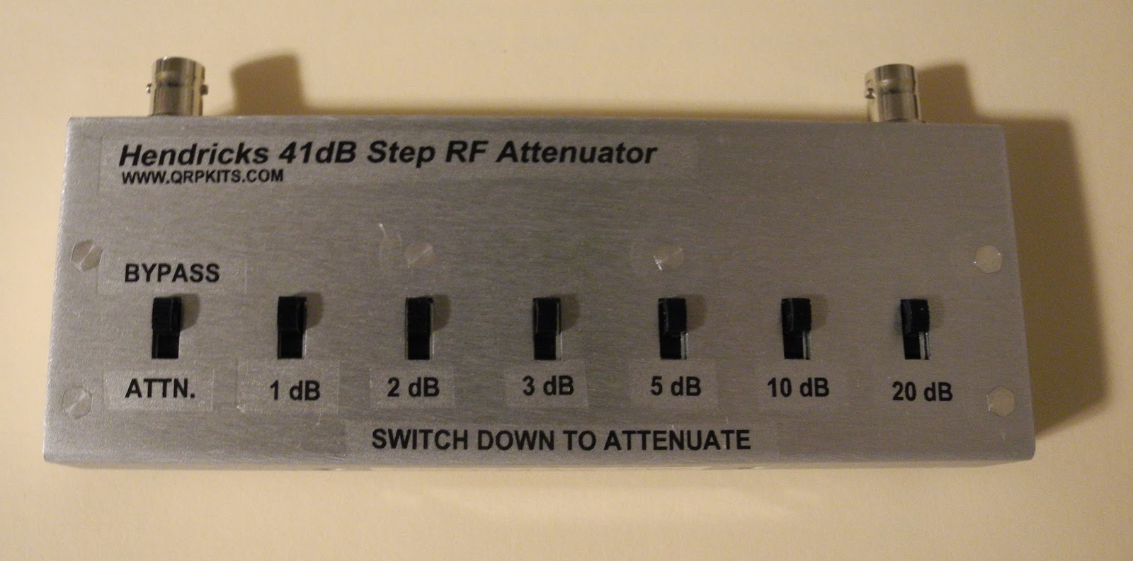
As we get into winter I'm starting to get back into some amateur radio projects. I recently built an RF attenuator kit  from Hendricks QRP Kits.

It's a nice simple attenuator that supports from 1 to 41 dB of attenuation with 50 ohm input and output impedance and can handle up to about 5 watts of power and is good to at least 30MHz. It's based on
a circuit in the ARRL Radio Amateur's Handbook.

Front View

Rear View
It only contains resistors and switches but comes with a nice silk-screened PCB and a metal case with decals for labelling the switches. It went together in an hour or so not counting the time spent waiting for the coats of Krylon clear coat finish to dry.

I plan to use it for a couple of applications. I have an RF signal generator built from a kit that has a fixed output. This will allow me to adjust the output level in 1 dB steps from 100% down to about .02% output level.

The other application, which it was designed primarily for, is to adjust the output level of a QRP transmitter so you can work at lower power levels with the flip of a few switches. The rear panel has a label which lists the percentage of output level and power output for 1W and 5W input) and various switch settings.

In may also come in handy when testing and calibrating ham radio and communications receivers.

Saturday, October 6, 2012

The Apple 1 Cassette Interface


The Apple Cassette Interface (ACI) was the only accessory sold for the Apple 1 computer. It allowed saving and loading programs from cassette tape using an inexpensive tape recorder.

Vince Briel  recently made a batch of replica ACI boards both as kits or pre-assembled. The board is similar to the original except using a more easily obtainable EEPROM chip rather than the ROM chips on the original design. I got one of the first batch of kits and assembled it.

ACI parts and manual ready to be assembled
I have a couple of tape recorders from that era. I have a GE model that I bought around 1980 and used with my Ohio Scientific Superboard computer for tape storage. I also recently picked up a Panasonic model from the 1970s or 1980s at a thrift store.  I don't the Panasonic RQ-2102 model that Apple originally recommended (amazingly it is still be manufactured and available).

GE Cassette Recorder circa 1980
Panasonic Recorder picked up a thrift shop
Panasonic RQ-2102 Recommended by Apple
The original Apple Cassette Interface manual is available on-line. The software is on-board the ACI and consists of only 256 bytes of code written by Woz. It is primitive and has no error detection. The later Apple II had a similar cassette interface circuit built into the motherboard (in models up to the Apple 2c). The Apple II used a similar storage scheme but added a checksum verification to detect errors.

Assembled ACI Replica
I haven't got mine to work reliably yet. I am working with some other kit builders to track down why. It is known to be tricky to get working. As well as a tape recorder I've been using my computer's sound card and an oscilloscope to debug it. I'll report more here on my progress toward getting it to work reliably. 

ACI Installed in the Replica 1

First Raspberry Pi Hardware Hacking


I did a little hardware hacking with the Raspberry Pi board.  It has some GPIO pins on a connector that can be used for hardware expansion. I bought two low cost kits from AdaFruit that make it easier to use the GPIO port.

The Pi Cobbler kit  provides a connector to the GPIO port and a ribbon cable that goes to a small breakout board that can plug into a solderless breadboard. It has all the pins nicely labelled. Below are a couple of pictures of my assembled board connected to a Raspberry Pi.

Pi Cobbler Plugged in to a mini Solderless Breadboard


Pi Cobbler Connected to Raspberry Pi Driving an LED

The Prototyping Pi Plate kit is a board which plugs onto the Raspberry Pi, similar to an Arduino Shield, that provides access to the GPIO pins via terminal blocks and provides a prototyping area for circuitry. I also purchased a mini solderless breadboard which can fit on the Pi Plate. A couple of pictures are shown below.
Pi Plate Mounted on Raspberry Pi
Driving an LED

Both kits went together easily in about 15 to 20 minutes with a little soldering. So far I have only had time to run simple programs to flash an LED driven by one of the GPIO lines (both shell script and C language versions). You can find lots of documentation and programming examples at this link.

I'm still waiting to receive my Gertboard, which is a more sophisticated input/output board for the Raspberry Pi that provides buffered input and output circuity and analog to digital and digital to analog converters. It also has an Arduino compatible chip on it.